Instructor: Ben Light
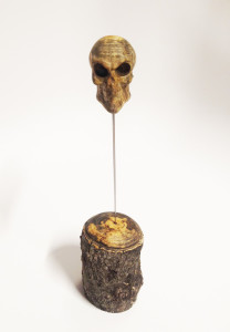
Final Presentation:
Week 14:
No air was milled on the roughing pass this time thanks to prep on the wood lathe.
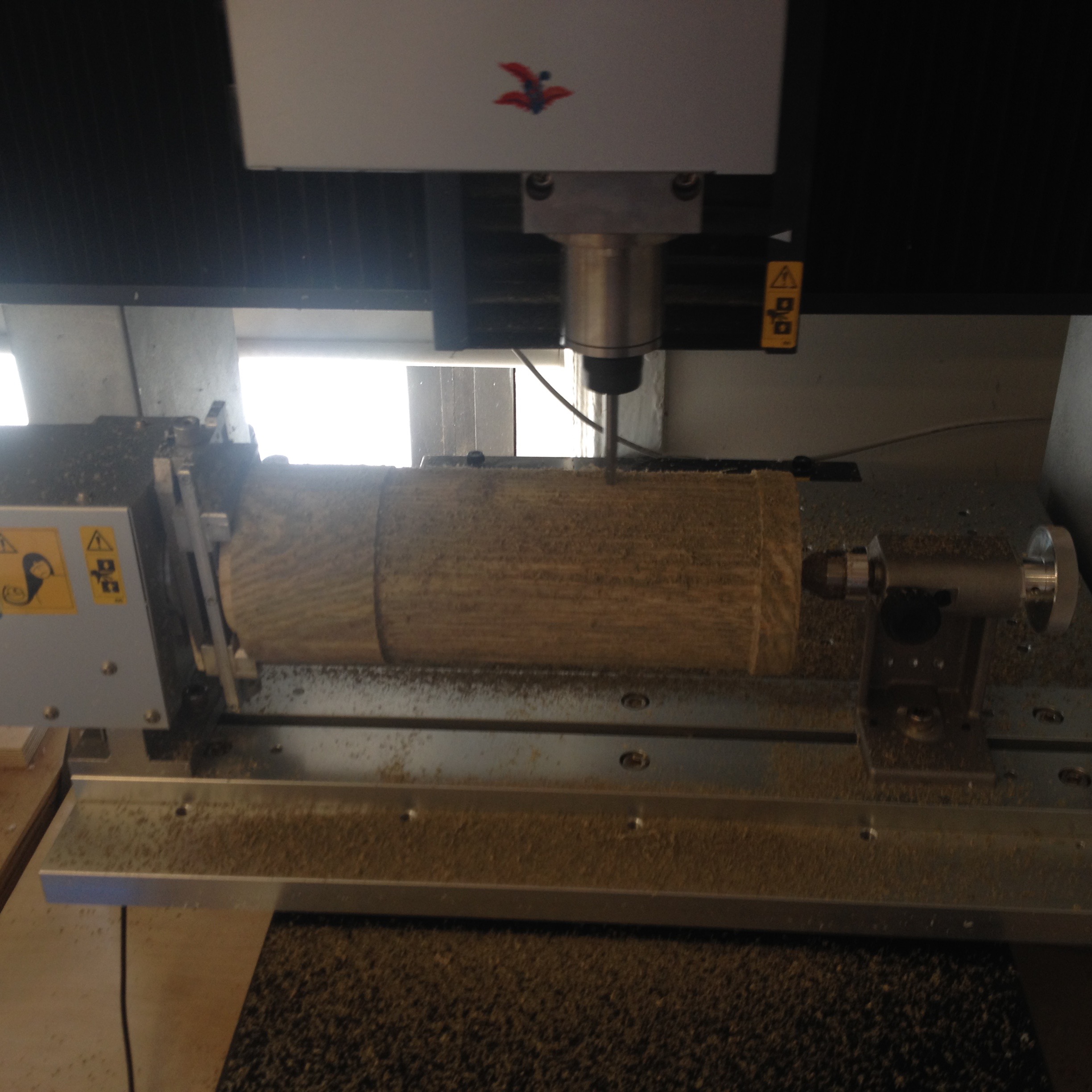
The roughing pass with the 1/4 inch round bit was very stringy, probably due to the wood being green.
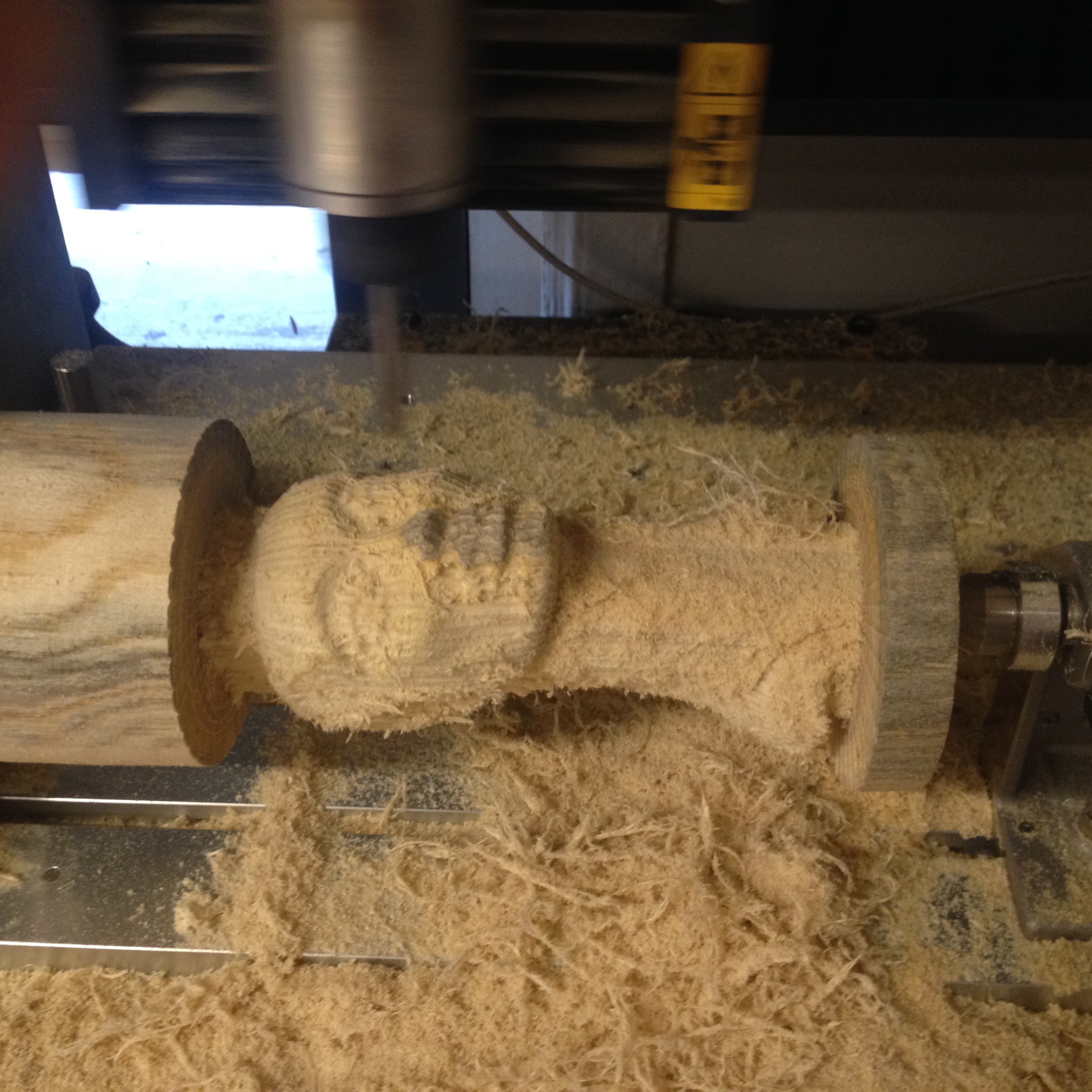
The first finishing pass with the 1/8 inch round bit took a long time. I had to leave the job paused overnight.
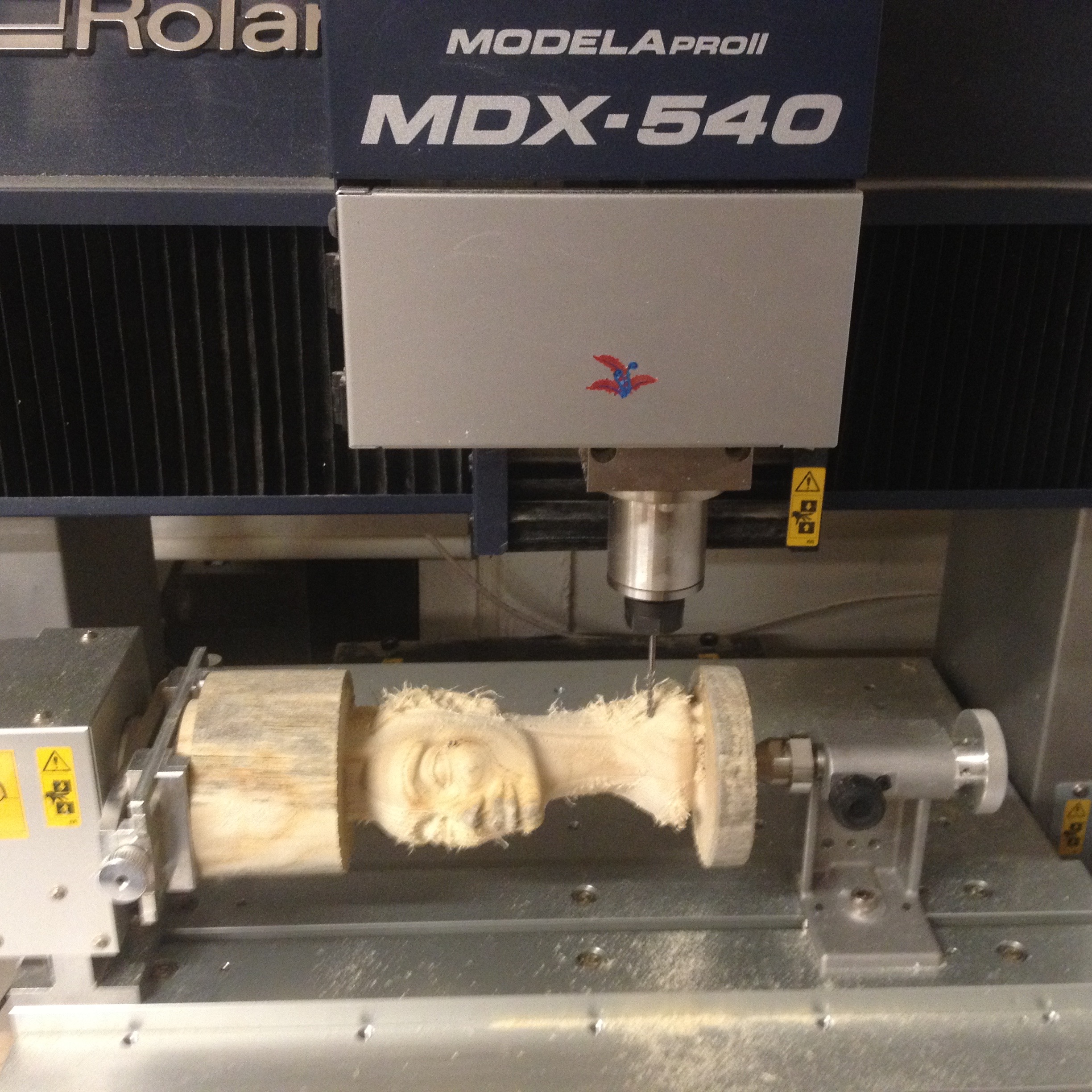
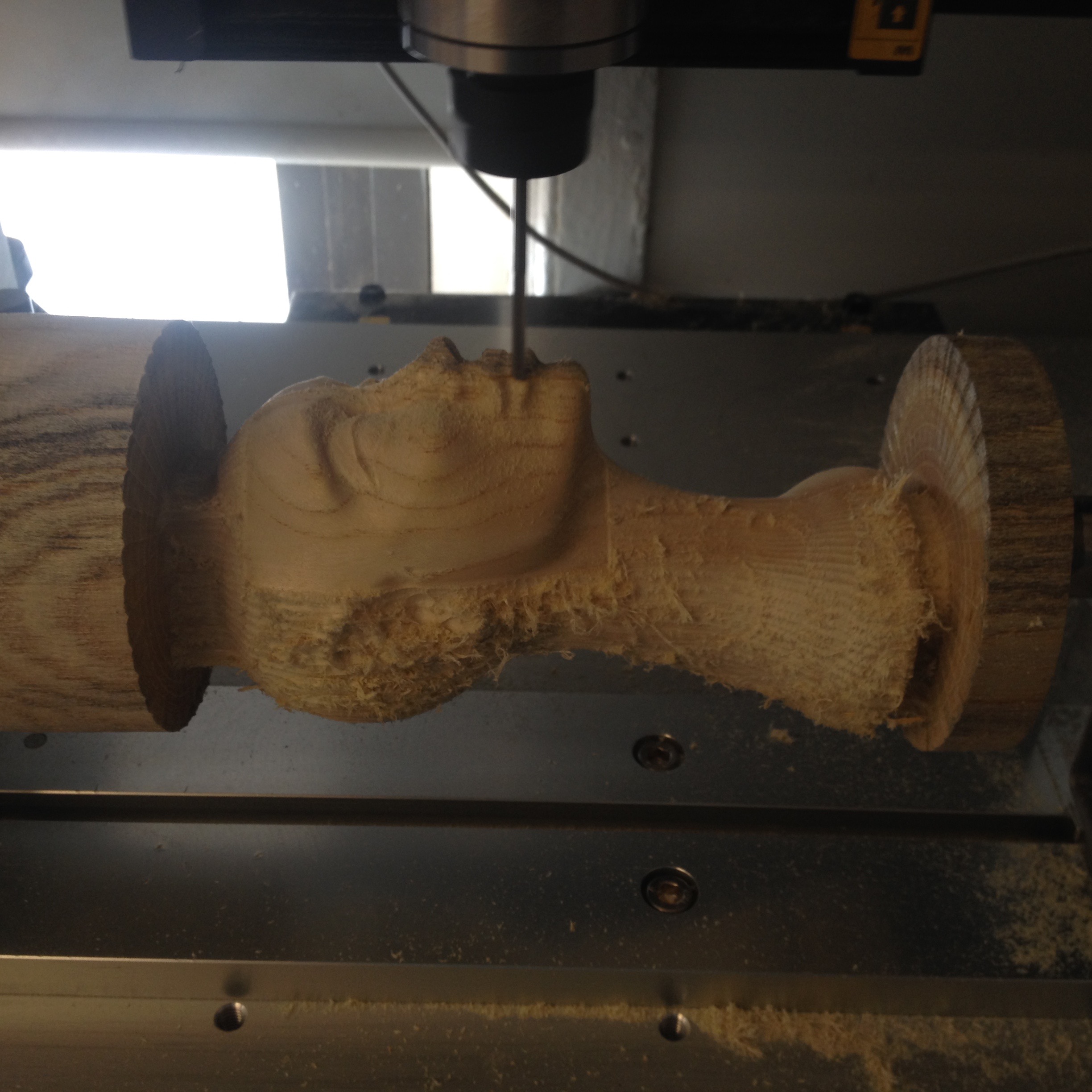
With some help from Ben, the job was adjusted to finish just the face.
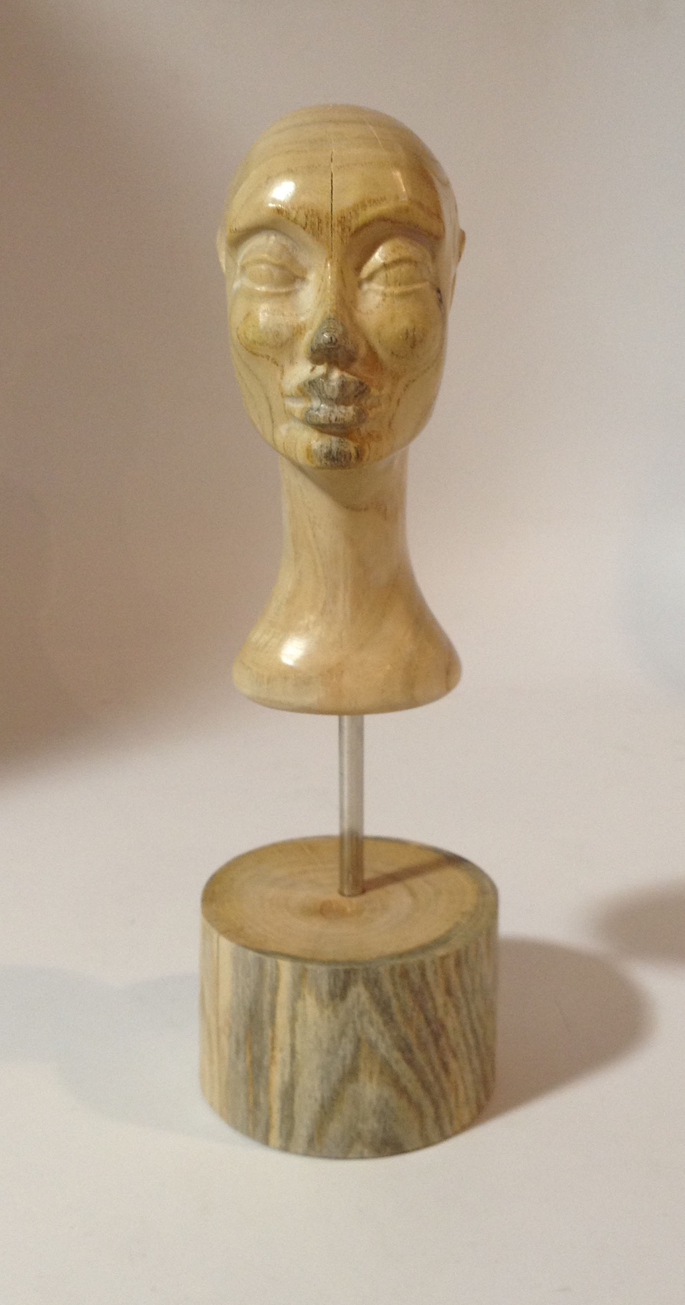
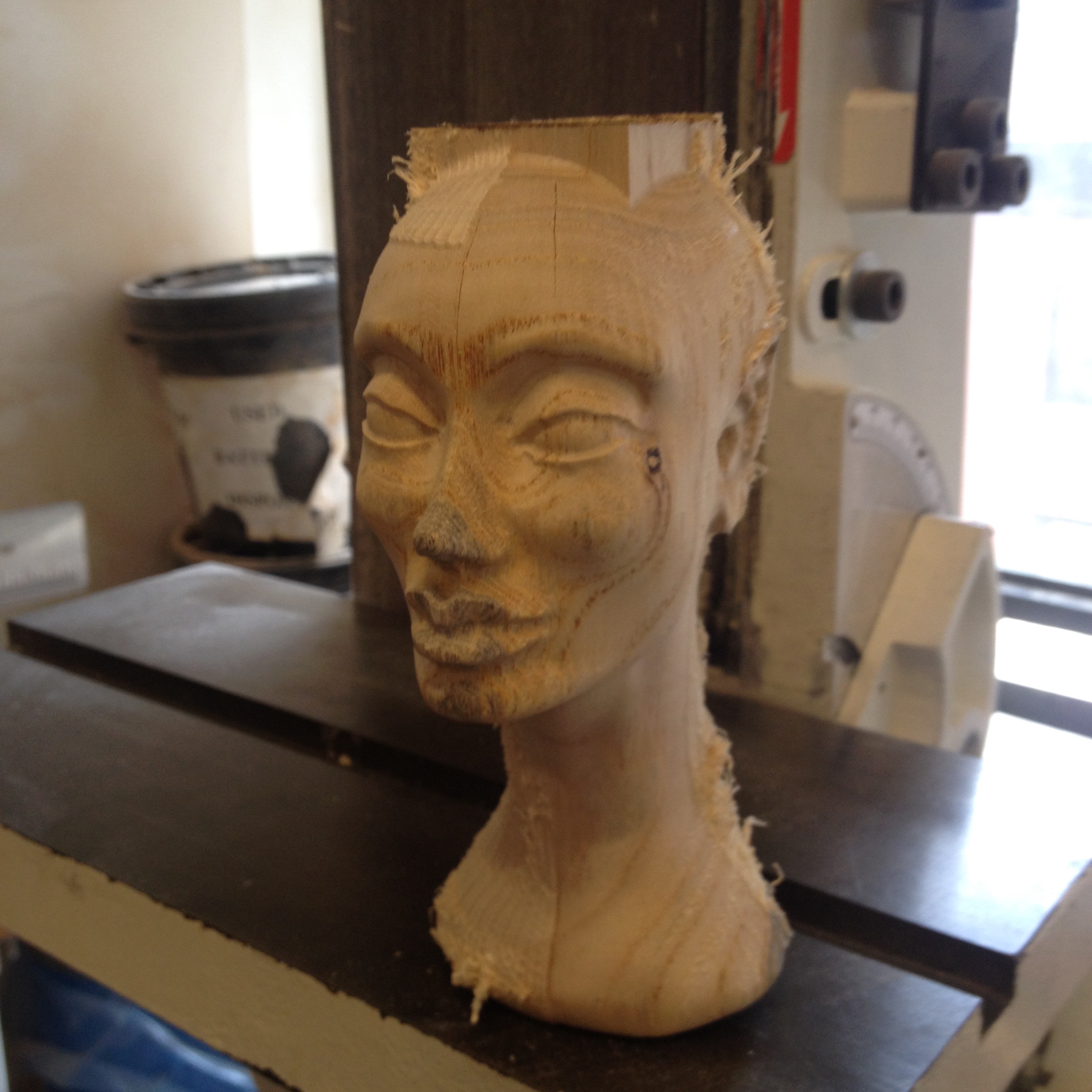
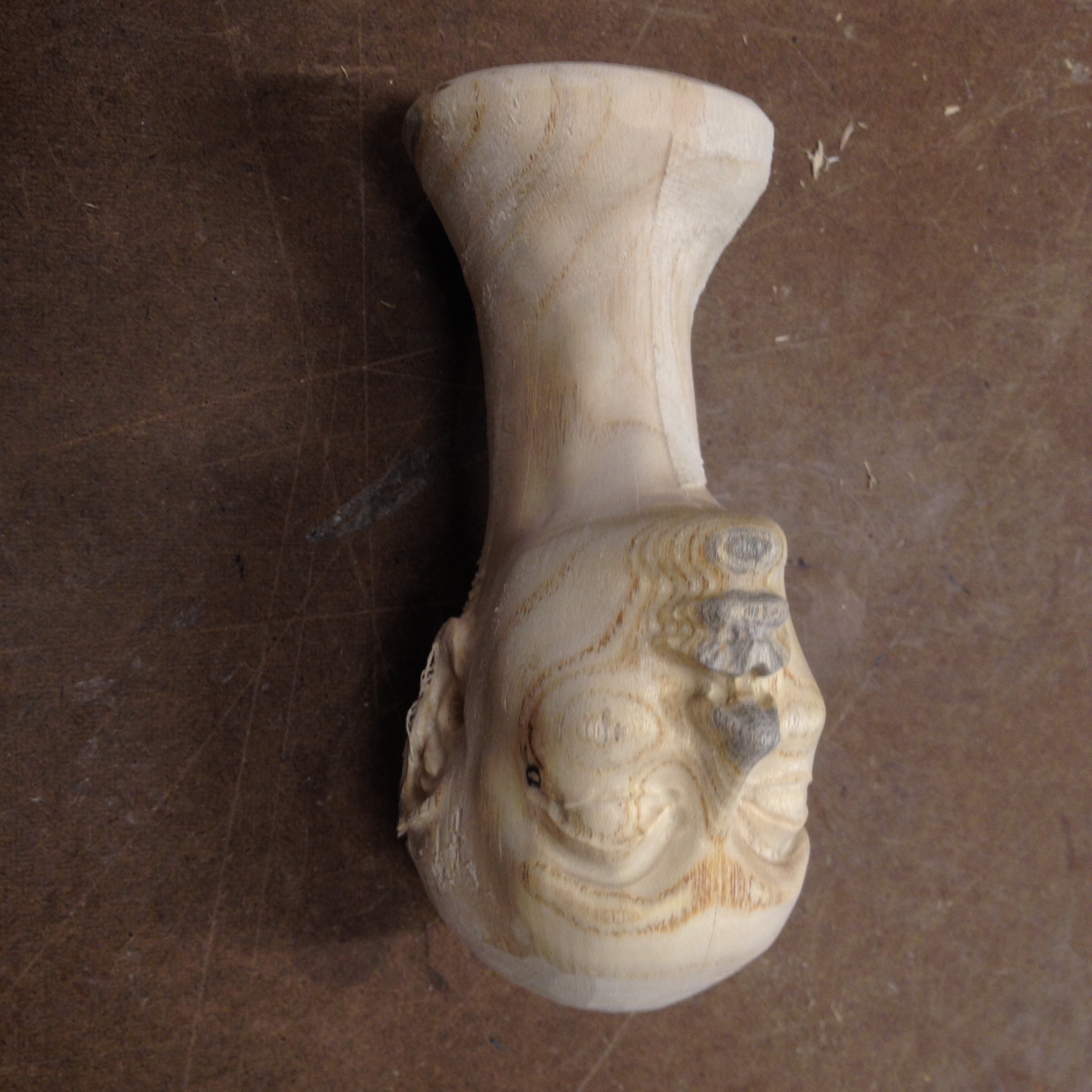
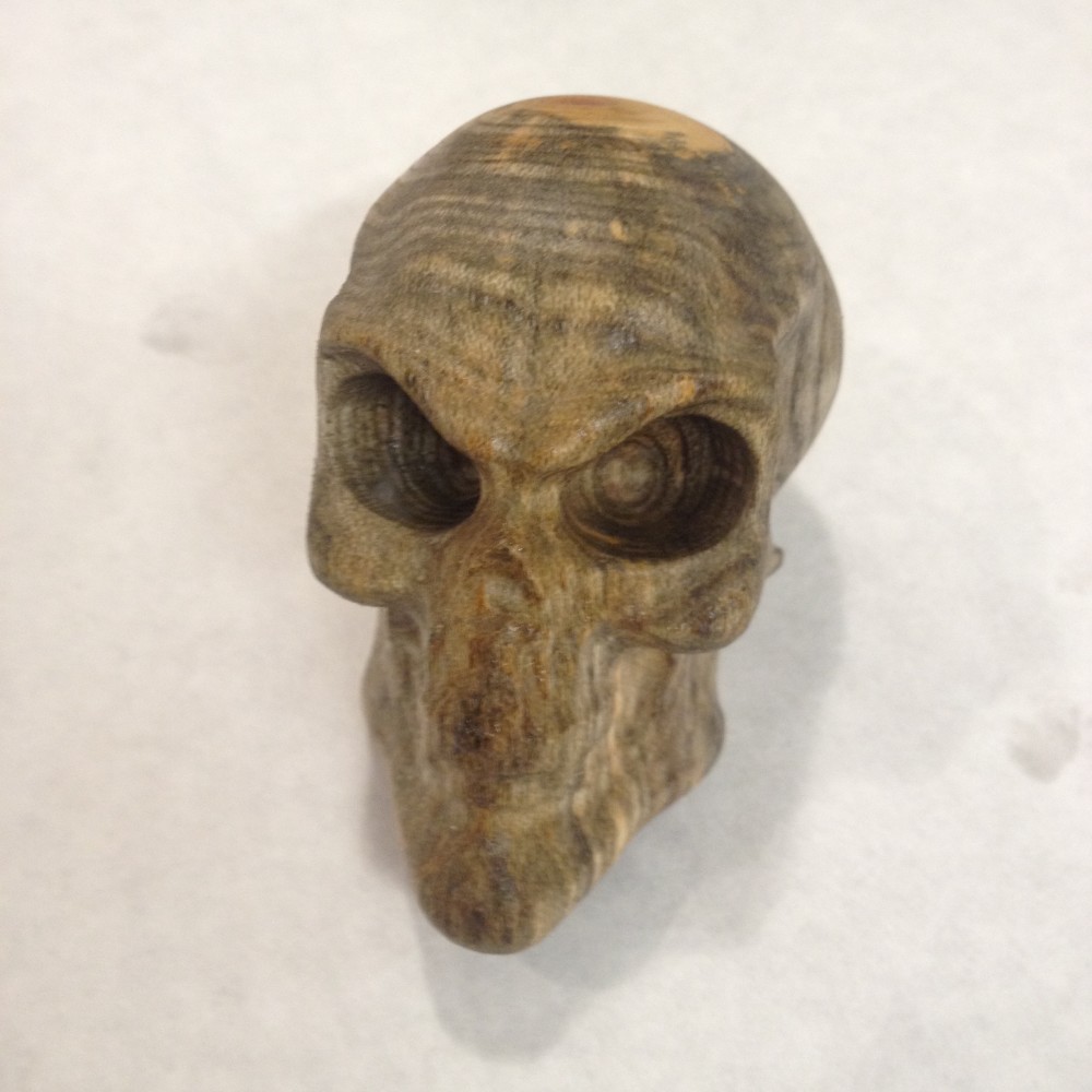
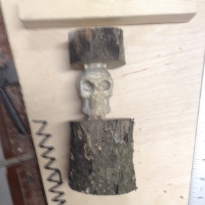
Here is what came off the 4 axis. You can see the difference between the roughing pass and the finishing pass on the forehead.
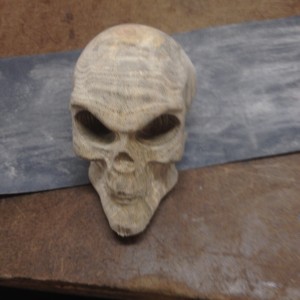
Lots of sanding later…
Even more sanding…
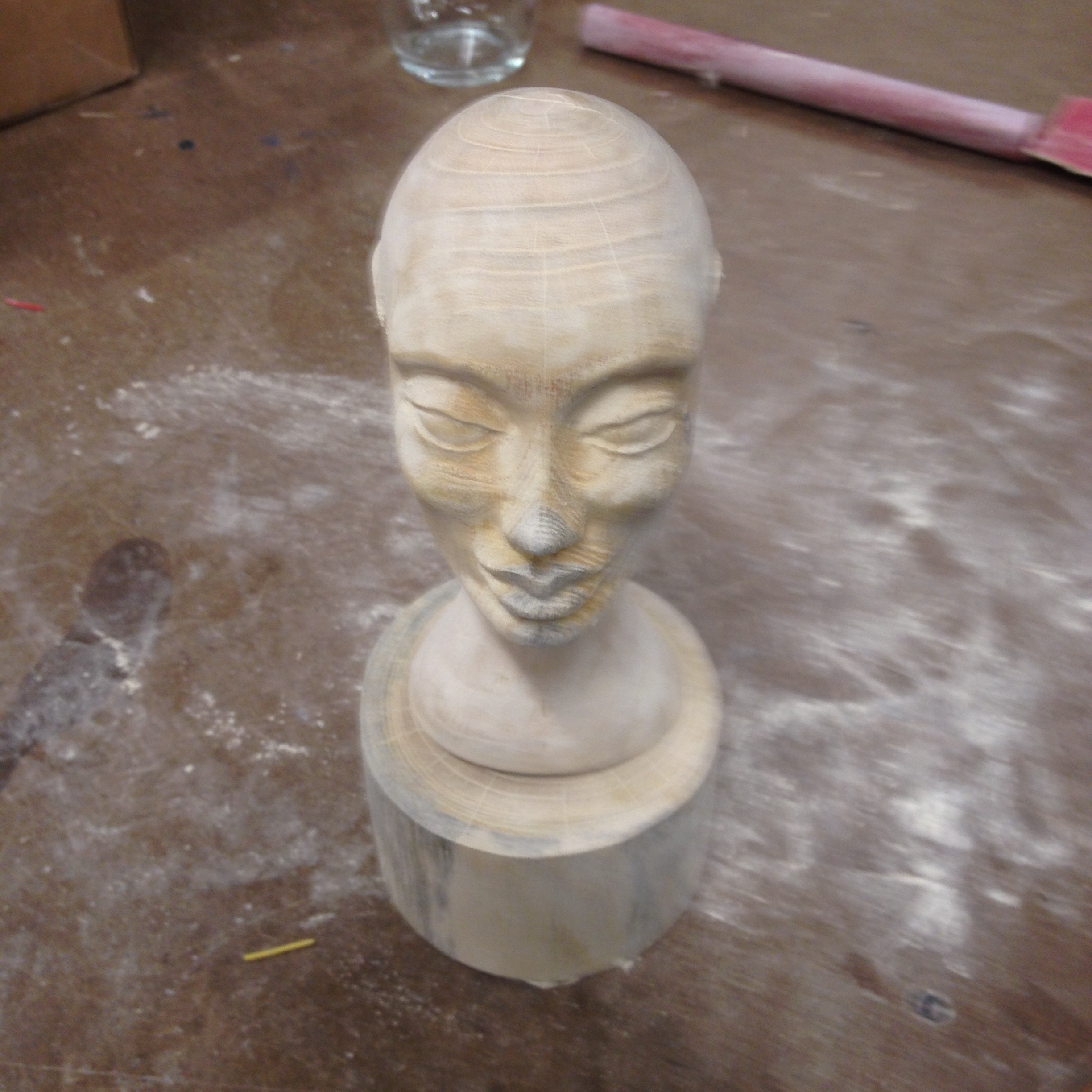
Lots of sanding and buffing…
Week 13:
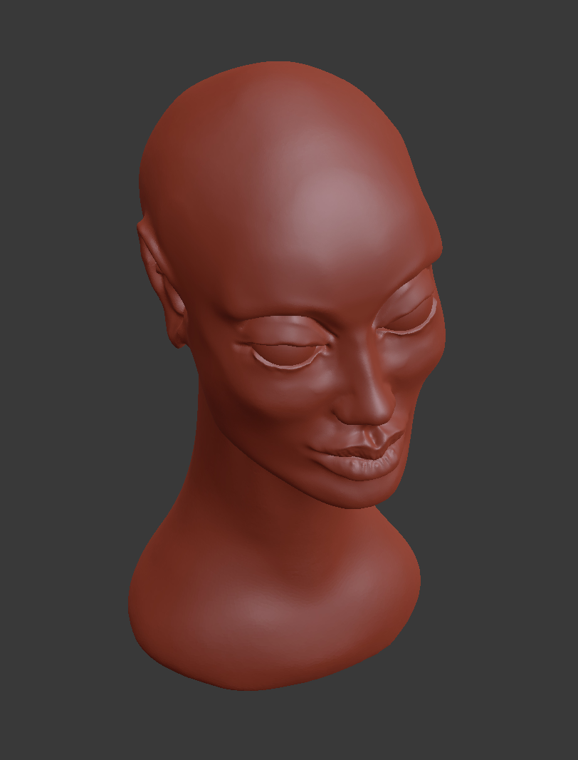
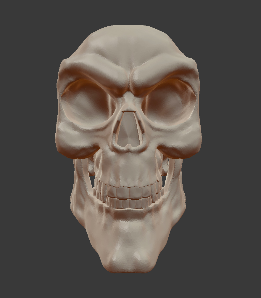
3D object sculpted in blender. Prepared in the roland software and ready to cut.
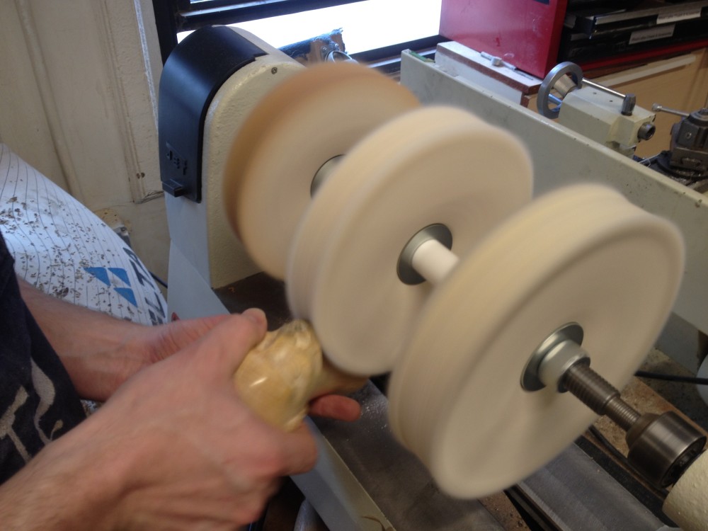
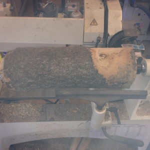
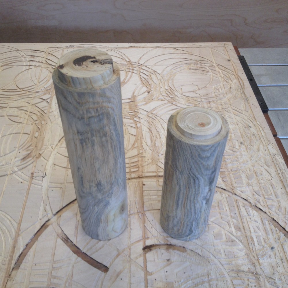
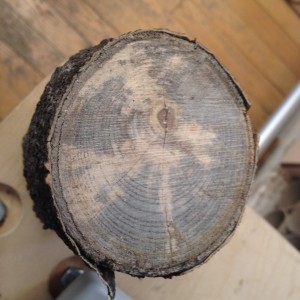
Two logs have been prepared on the wood lathe for the 4-axis.
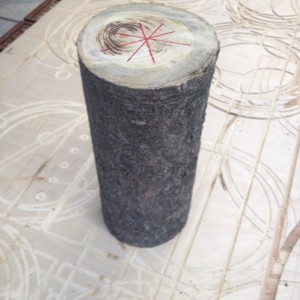
Marking the center point.
Roughing the cylinder.
Shaped attachment points.
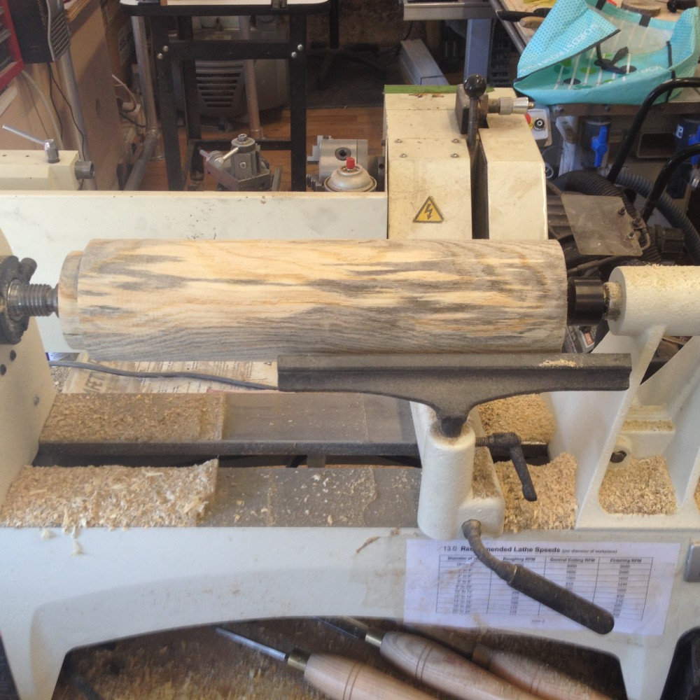
Finished blanks.
Week 12:
Wood Lathe has arrived!
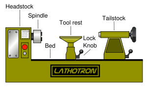
Swing = max diameter of the material the lathe can handle. Lathe tools must be sharpened continuously because they are in constant contact with the material. Face shield at all times. Paper mask also a must.
Start lathe at lower speed, especially with a new piece of stock. Starting is the hardest, once the piece is roughed down to center the chatter will die down and smooth out.
Week 11:
Lots of sanding later I found an unmarked container of food safe cutting block wax.
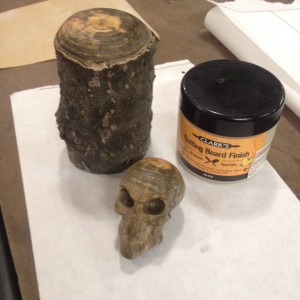
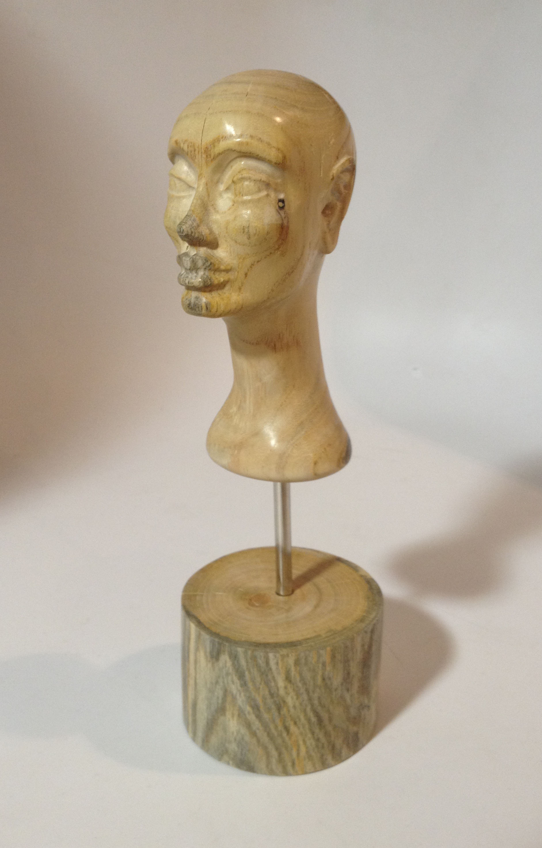
Not too shabby!
And on the stand for presentation.
Week 10:
CNC 4-Axis skillbuilder 3D Part II
Sunday is a good day for open slots!
Here is what I am going to try to get out of a piece of 3 inch diameter rough wood:
I found some dry, cut up limbs near my apartment and selected one that was about 3 inches in diameter, bark, spalting, the works.
I set the program to mill air for a while due to the material not being a perfect cylinder.
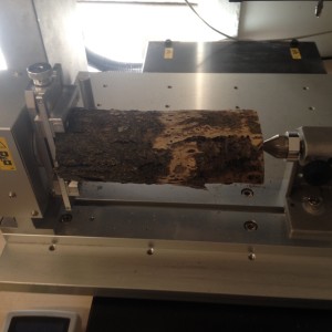
Roughing pass:
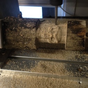
Fresh off the machine.
Rough sanding done, on to the finishing:
Week 9:
CNC 4-Axis skillbuilder 3D Part I
The bottleneck on the 4-Axis is the worst one of all the shop tools, largely because the machine and the software are in the same location and cannot be used independently.
So my goal with this skillbuilder is to make it fast!
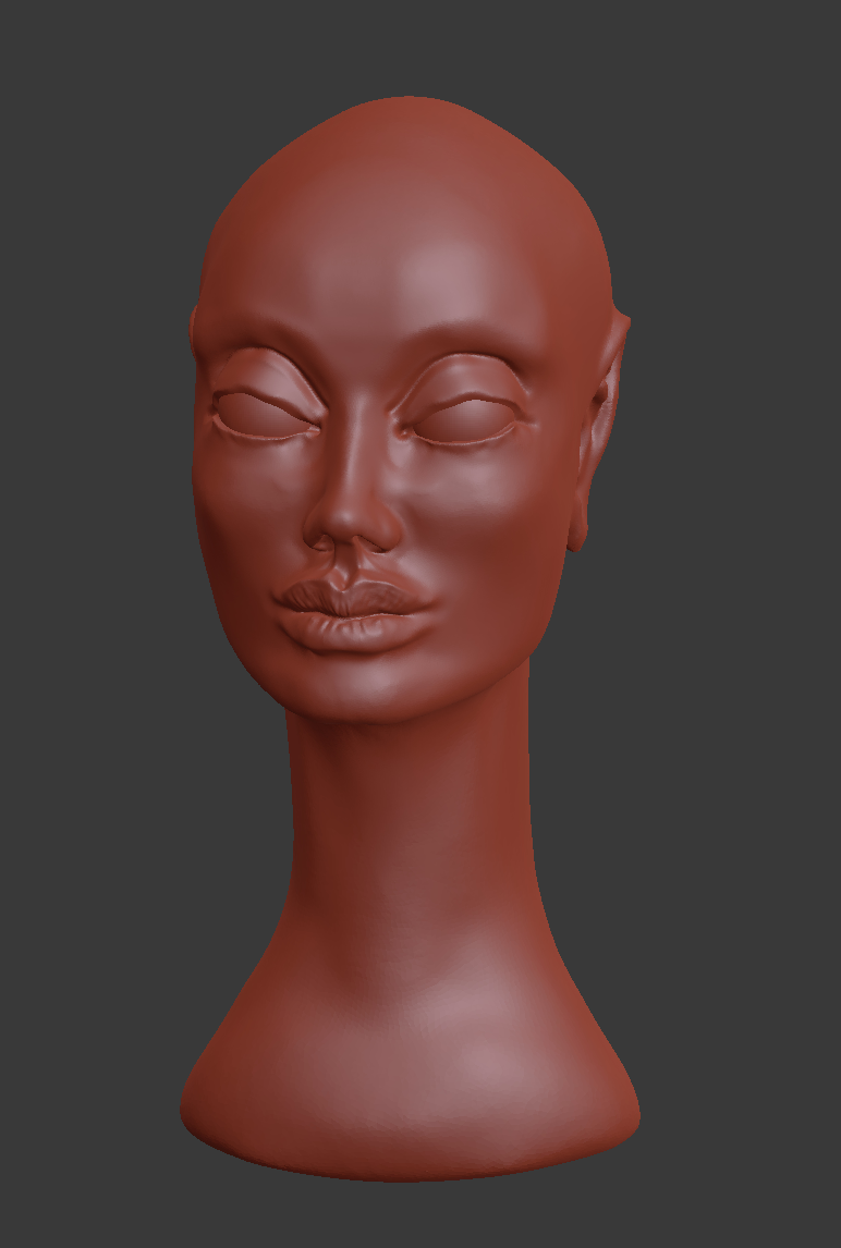
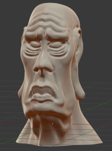
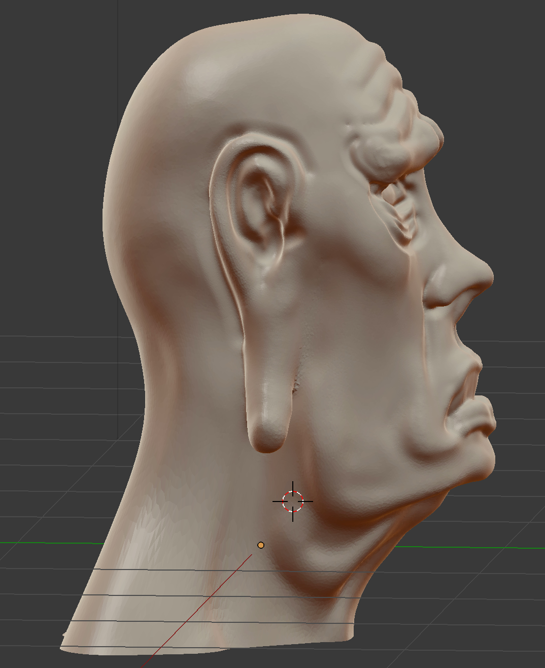
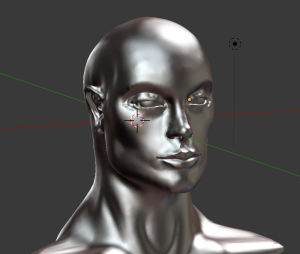
First I created a new bust with more stylized features.
Next I applied the following steps to make sure it would print as fast as possible:
-Small part
-Large bit (1/4 inch ball)
-Super soft material (artist’s carvable foam from Blick $5.00)
-Optimized settings
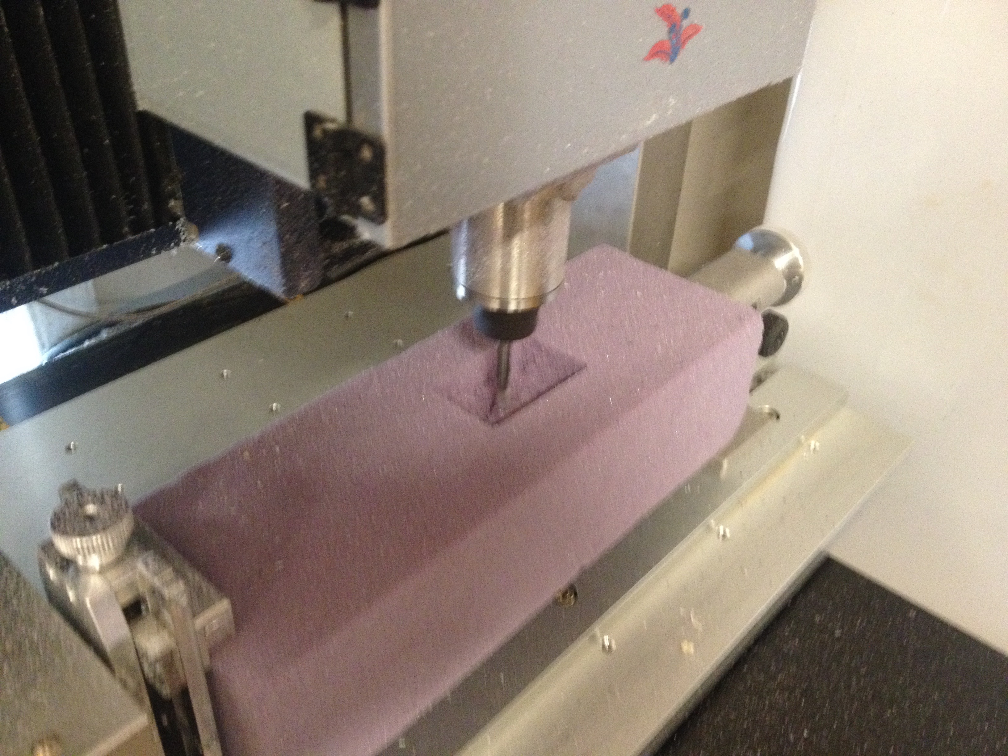
Less than 20 minutes total cutting time! It was like cutting foamed air.
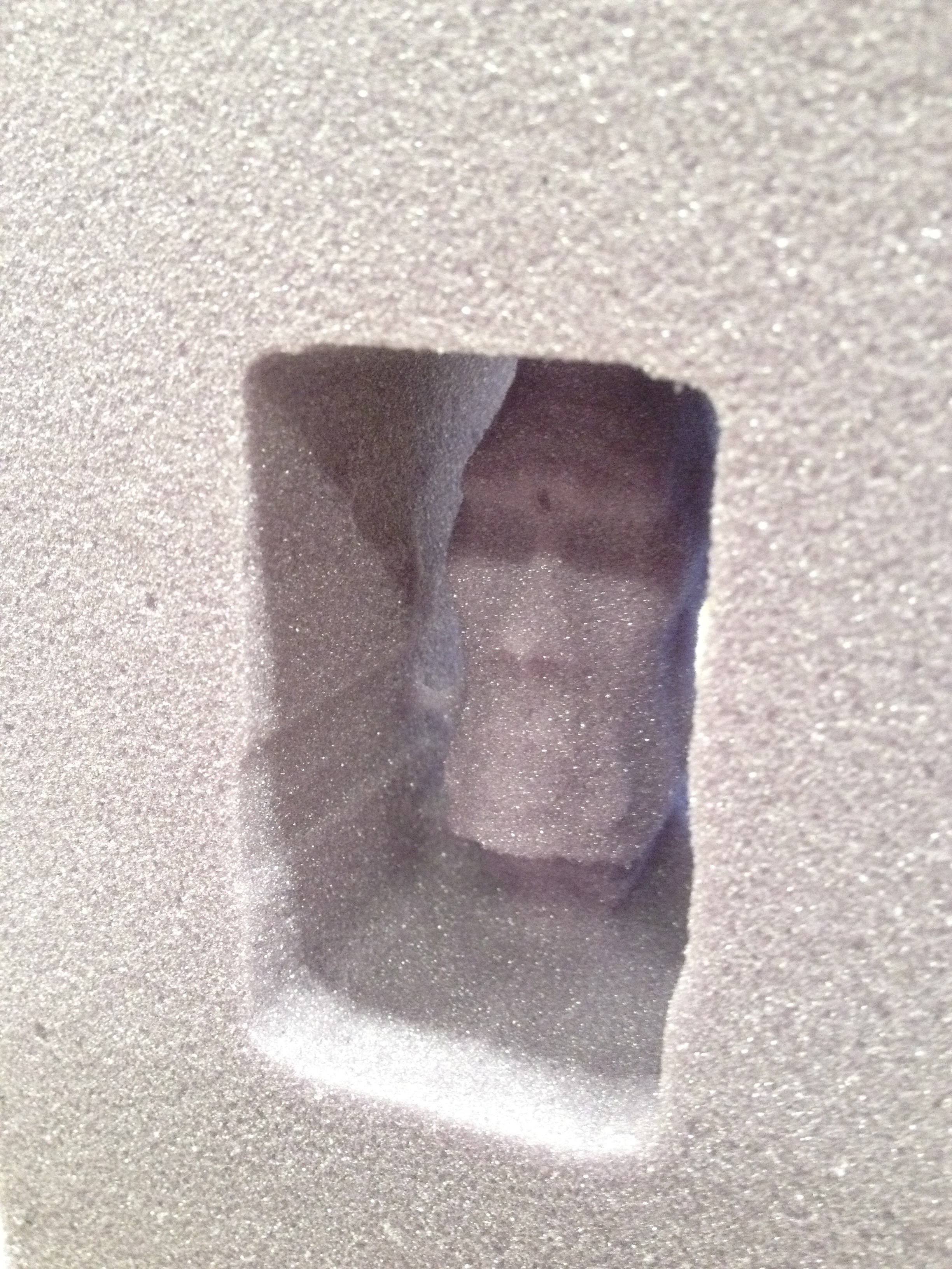
Peekaboo!
Week 8:
Update on projection table:
Also did some more metal lathe stuff:
4 Axis CNC
Administrator: (Spacebar once)
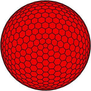
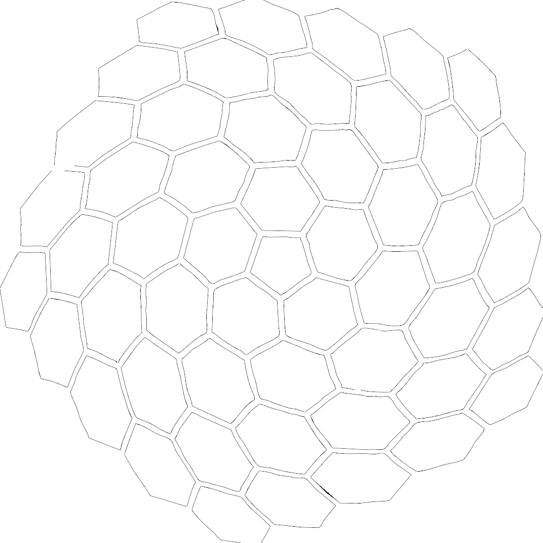
Two possible files for the 4-axis:
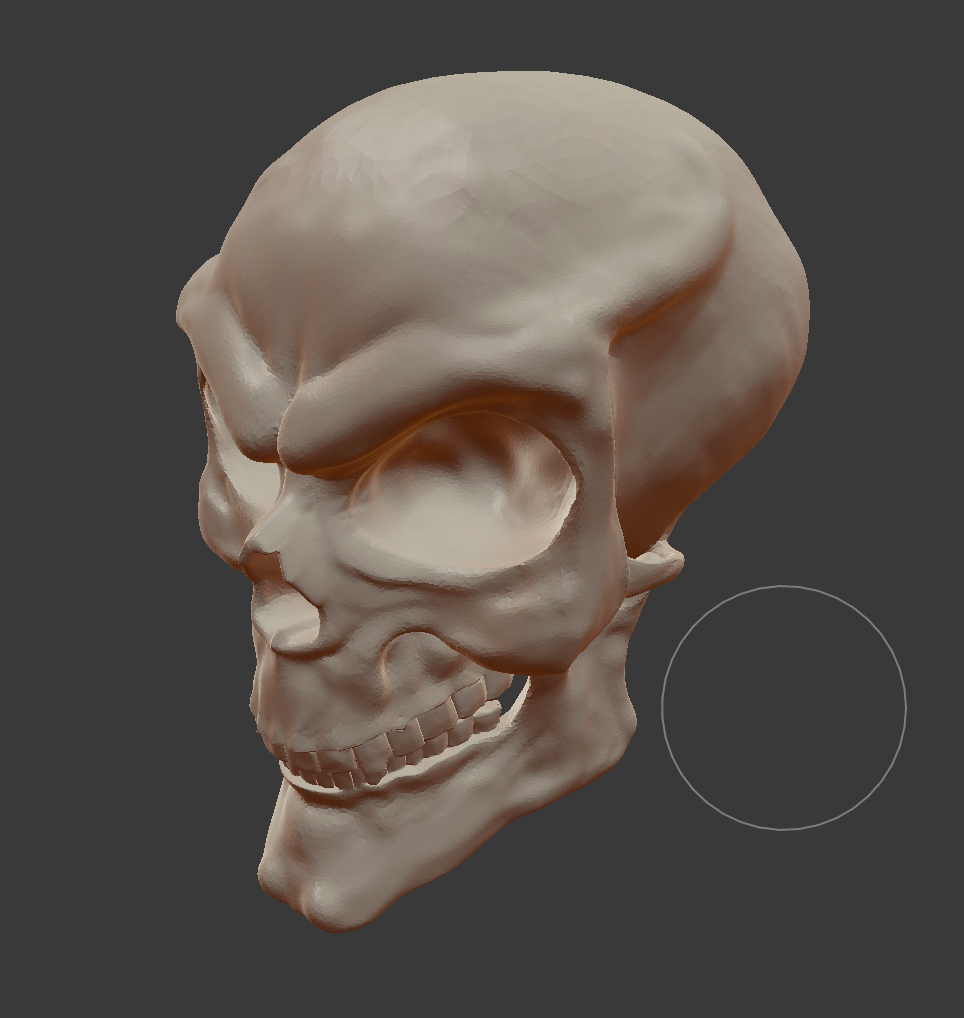
Mesh sculpt from Blender:
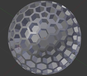
Mesh hex ball from Blender:
Week 7:
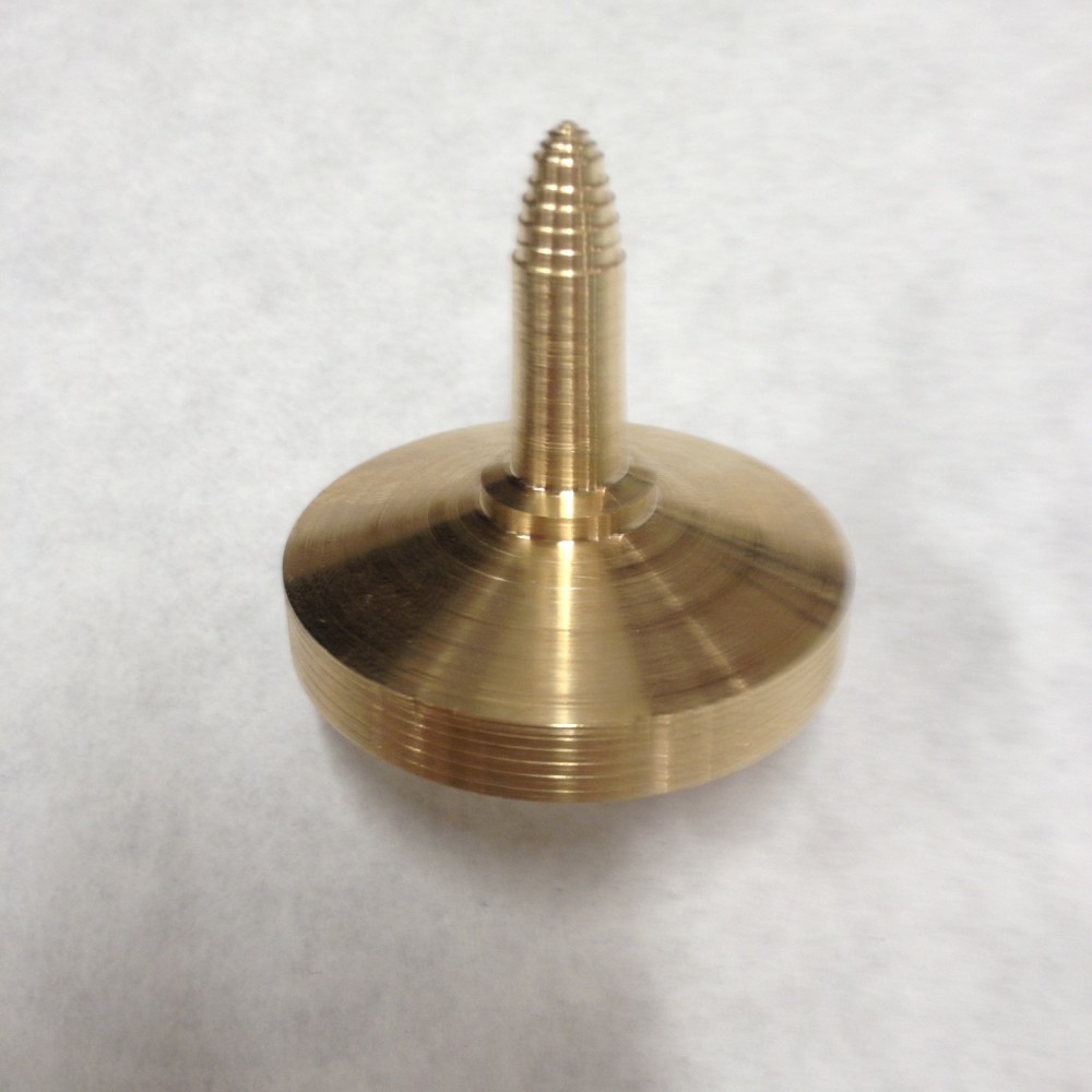
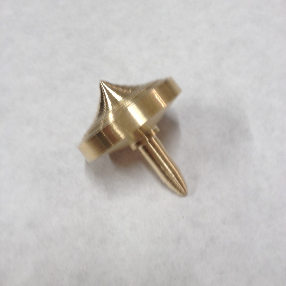
Metal Lathe skill builder and doo-dad:
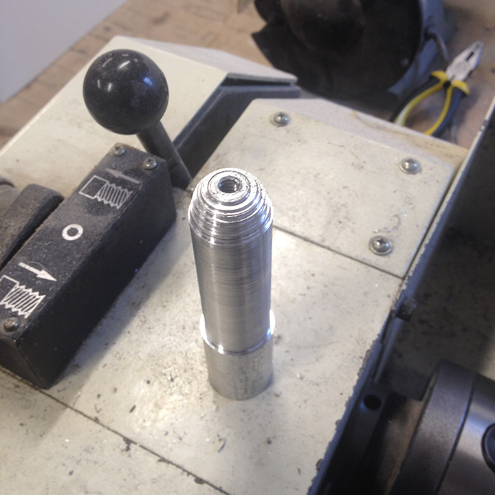
First I flush cut the face of one side and remounted it. Cut down the other side and shaped down a dome with repeated, incremental cuts. Drilled out the center per instructions, and cut the threads.
Then carefully, gradually made the cleaving cut.
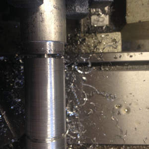
Took it down to about a 1/4 inch and finished the rest with a hacksaw.
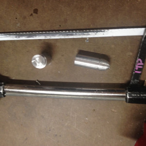
Reversed the piece, cleaned up the other end, and drilled out another hole.
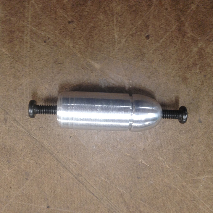
Threaded the other hole. Sandpapered and polished the piece.Tested the threads with machine screws. Yes, I know, it’s a bit phallic. I was thinking bullet but ended up with more of a mullet shape.
Metal lathe: Very dangerous piece of machinery. Never leave the chuck key in the chuck; it is a loaded gun. Always use cutting oil. Cut slowly, make cuts small and shallow. The machine is made for precision, not big moves. Keep emergency stop button pushed in when not in use.
Week 6:
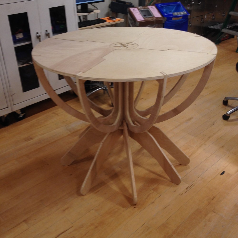
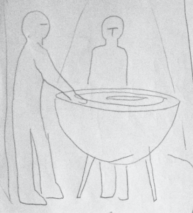
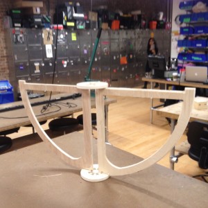
Midterm Project: Half Sphere Projection Table
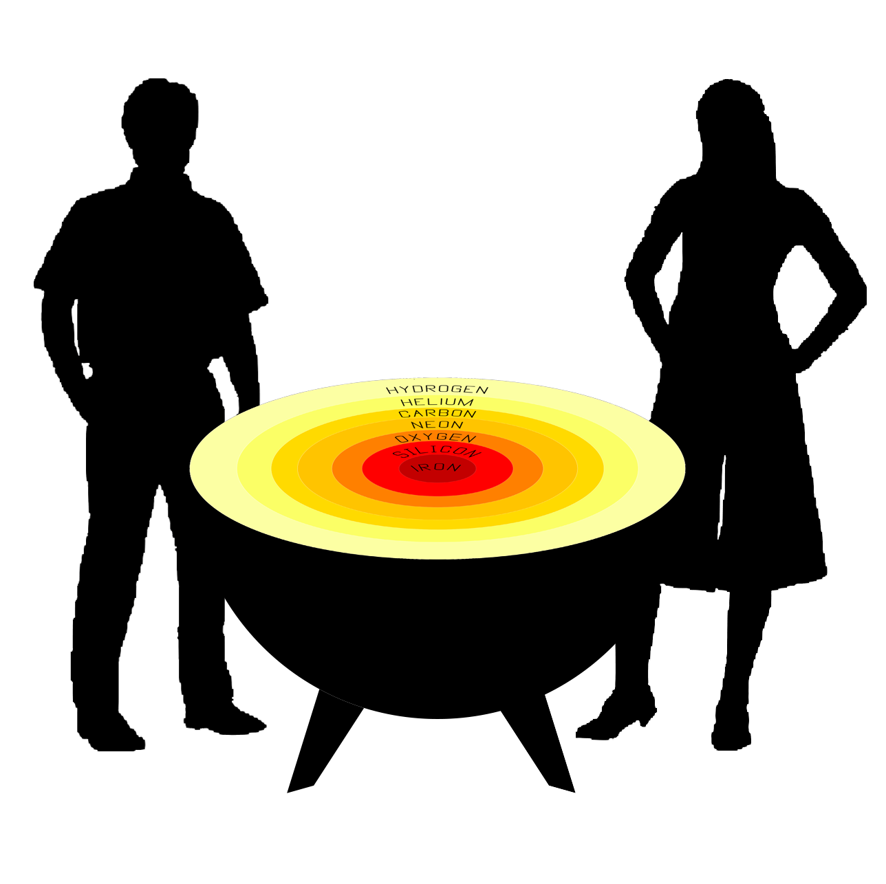
This will be the eventual installation of the Projection Table, as a part of an pop up exhibit on Stellar Forensics. Still deciding on whether to do legs or suspend it from the ceiling.
Here is the assembled piece, no fasteners or adhesives used to set it up. Four feet in diameter, two feet high.
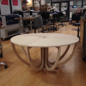
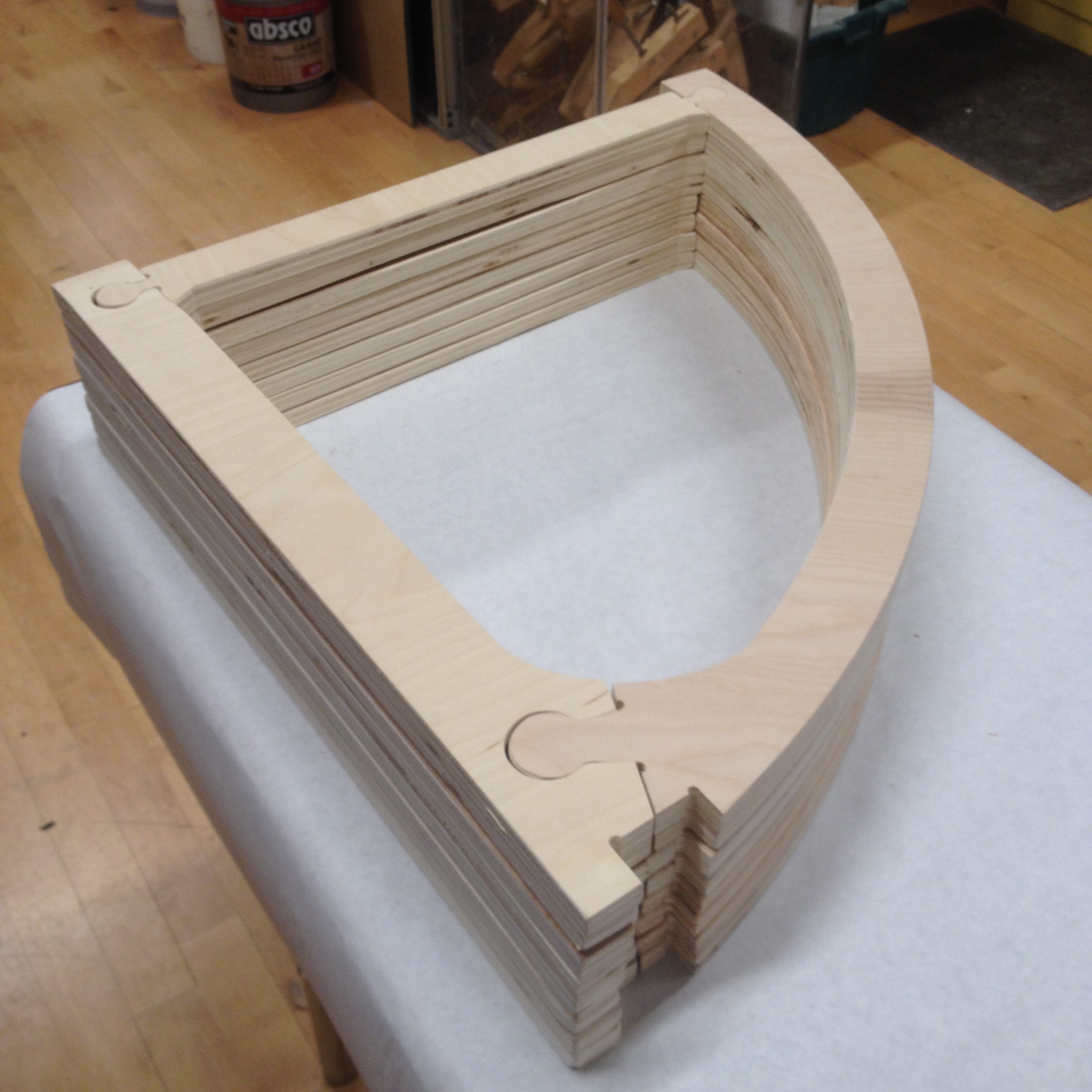
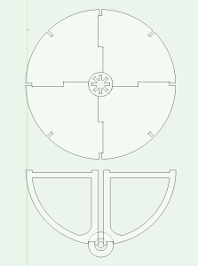
It is assembled from four different types of pieces that interlock:
-Two key joint disks
-Four table top slabs
-Eight spokes/ribs
All fourteen pieces pack down to 2 feet x 2 feet x 9 inches.
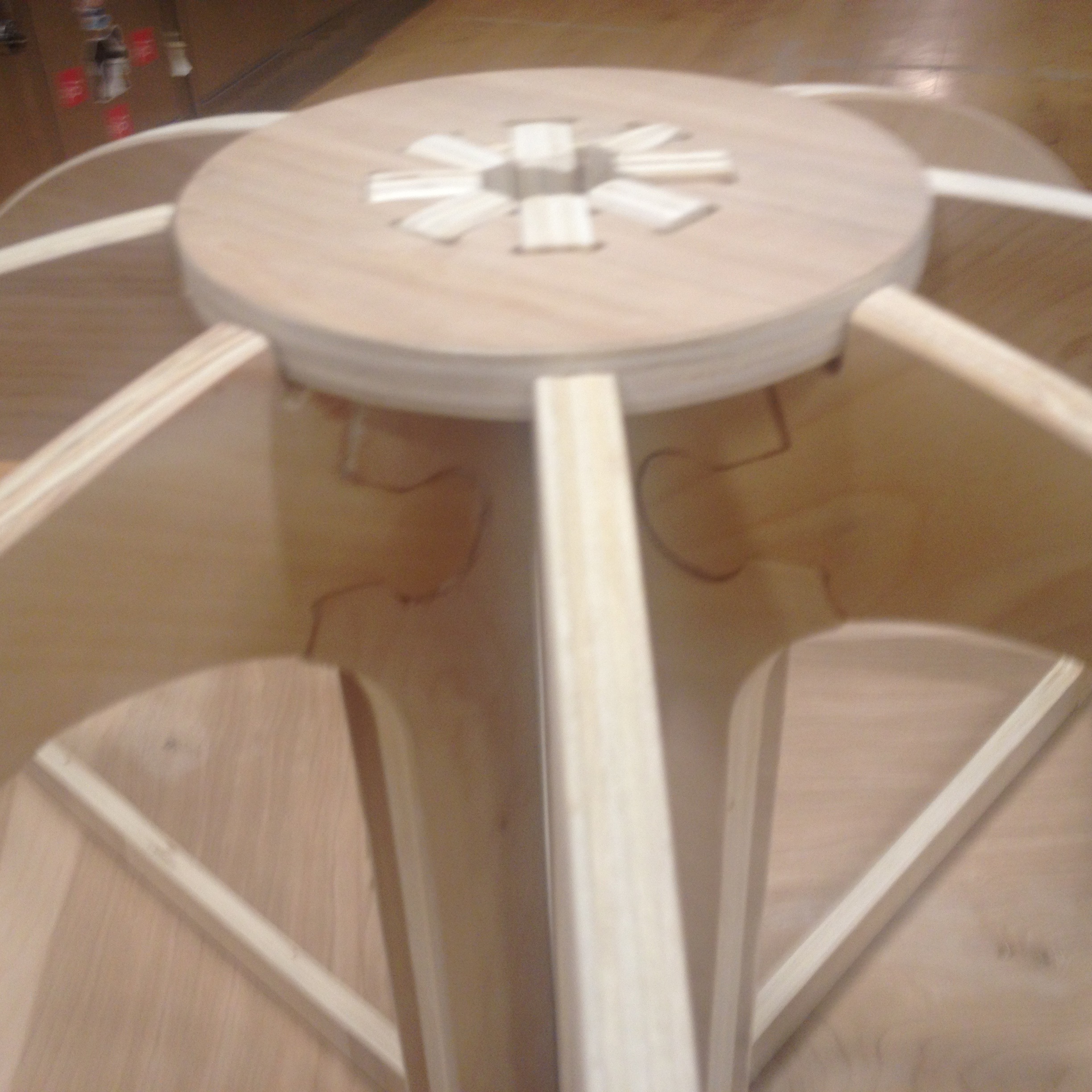
This is the underside, the light patches are wood filler to smooth out the spoke/rib joints
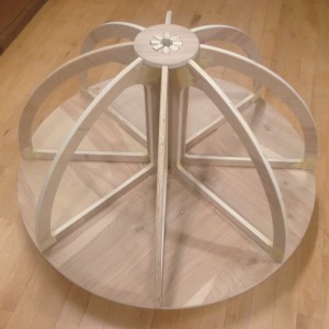
They were pretty noticeable before filling and sanding. The design and the CNC tolerances probably still need tweaking. To make everything fit required a significant amount of sanding.
These are the spoke/ribs after being glued together from their constituent parts. Doing it this way saved on material but did increase the time and effort to complete the project.
I learned a lot from doing this project. Next time I am going to keep the finish work in mind during the planning phase in order to minimize the amount of time sanding and fitting.
Week 5:
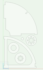
Midterm Project Proposal: Half Sphere Projection Table
What I am hoping to accomplish is a 4 foot diameter table that can be assembled from smaller, more portable pieces without tools.
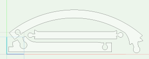
I sketched the design out several times on butcher paper before opening Vectorworks. Eight quarter circle sections lock into two slotted rings. The tabletop is made of four pieces that fit into and reinforce the ribs.
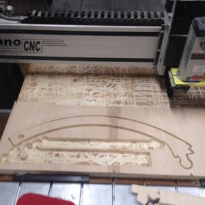
The first round on the CNC was pretty rough. The plywood was very warped and the mill bit did not make it all the way through the material on several of the cuts.
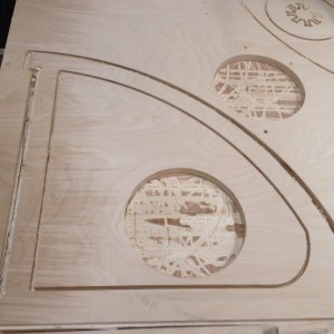
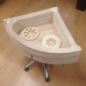
I was able to get the key circular joints done cleanly and I had enough to do a proof of concept.
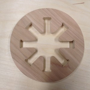
I used up a lot of material to make the ribs as a solid. I decided to break it up into pieces which I will glue together later.
To make sure the pieces would fit I did a successful test on the laser cutter
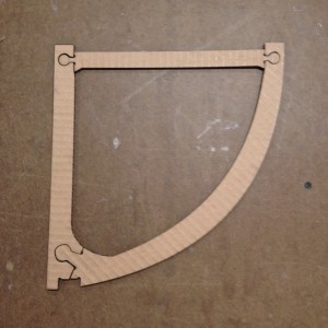
This layout used much less wood. The pieces required some sanding but fit together pretty well for their first round. After some adjustments I think they will glue together nicely.
Week 4:
Joinery and assembly with the CNC.
Digital CNC joinery has to compensate for the lack of sharp corners. Rounded corners are the norm. For fitted parts make holes slightly larger than bit radius.
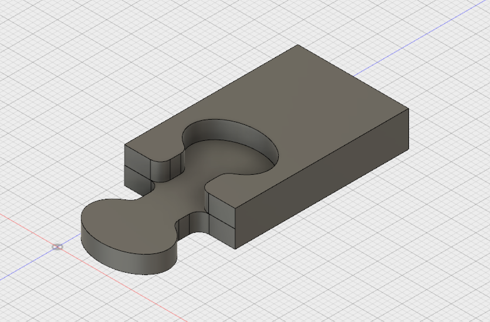
For the skillbuilder assignment I wanted to do a custom joint. It took several trips back and forth between vectorworks and mastercam.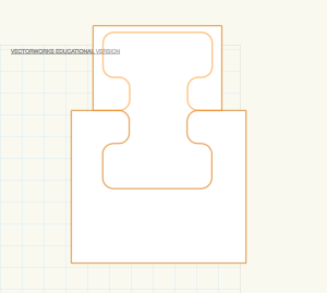
I also built the part in Fusion 360. I took a class last semester called Prototype to Fabrication which introduced Fusion 360 to the class. There are parts of the software that I like but I also find myself frustrated by a lack of certain operations that I have access to in other 3D Animation programs like Softimage XSI or Blender. The CAM integration in Fusion 360 worked well right up until I tried to export the numerical file; which cause the program to crash repeatedly.
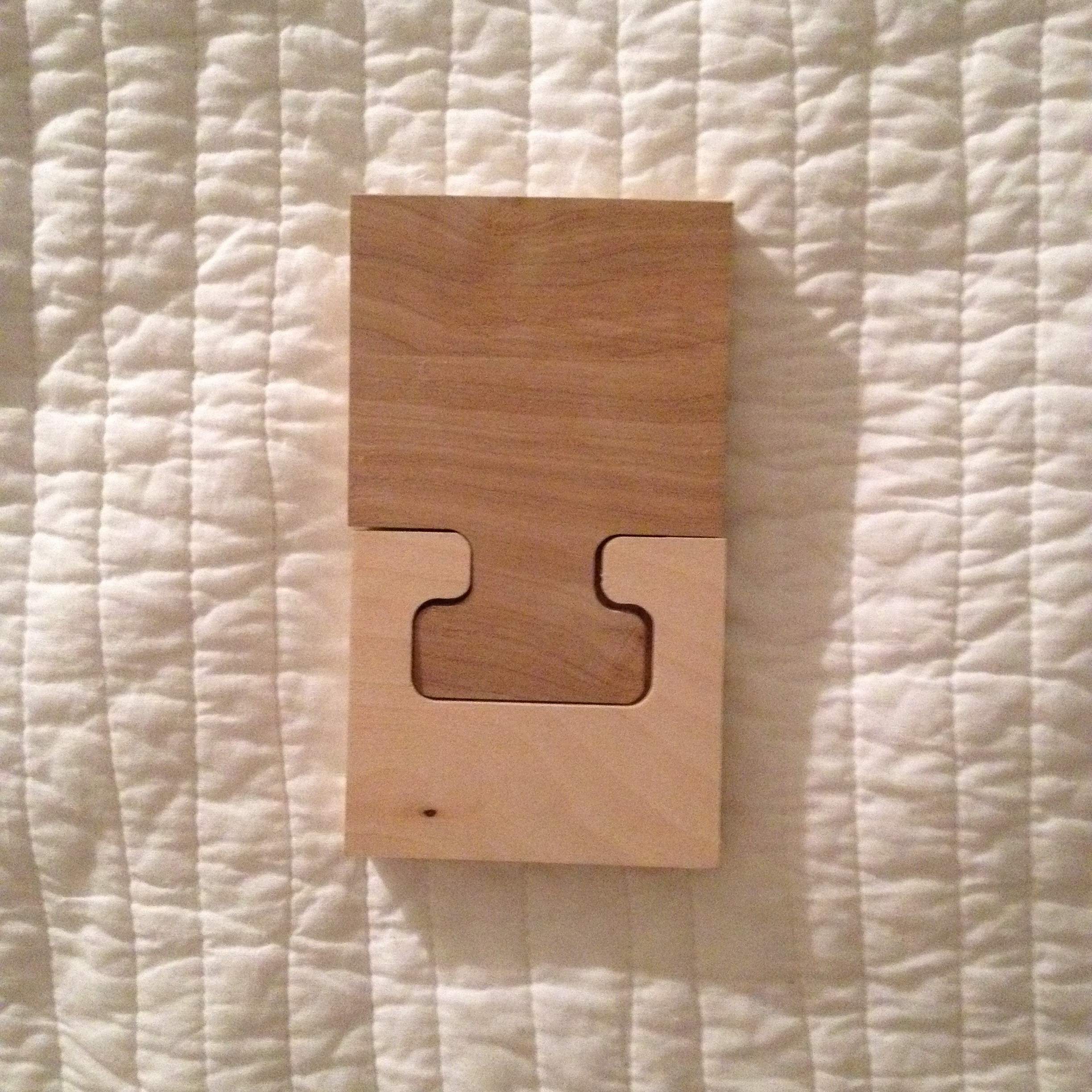
After one false start I got the CNC to do it’s thing. It really does take a few runs to get the workflow correct. Cut the pockets first.
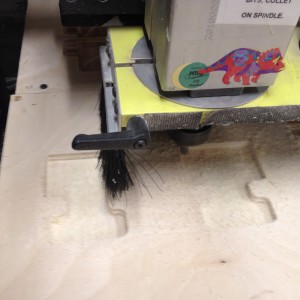
Then the contour cut.
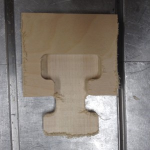
Upcut bit was kinder to the reverse side
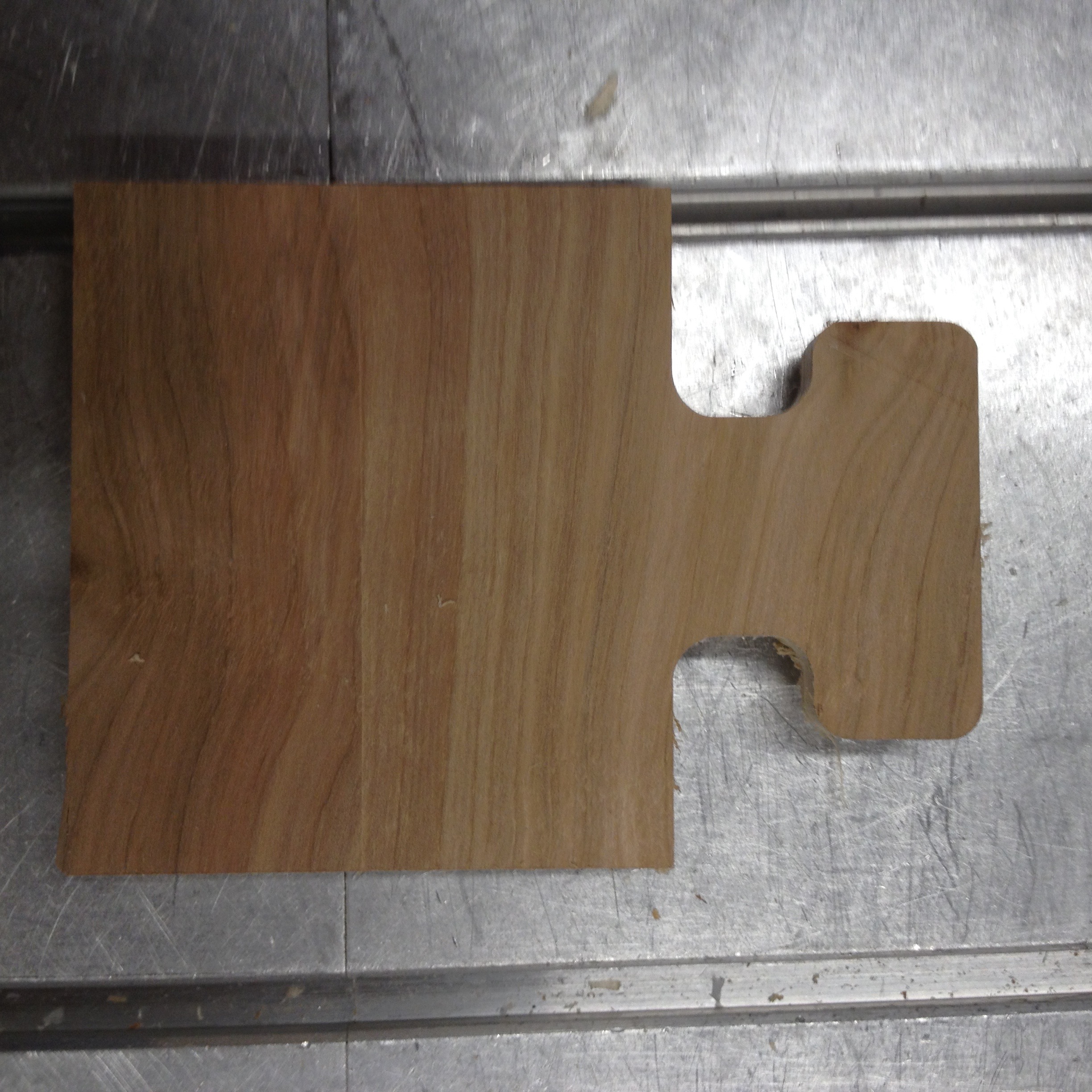
There is way too much play in the joint; although I am certain I can rectify the issues if I adjust the drawing and settings.
Week 3:
CAD, CAM, and CNC. Lots of back and forth to refine the job.
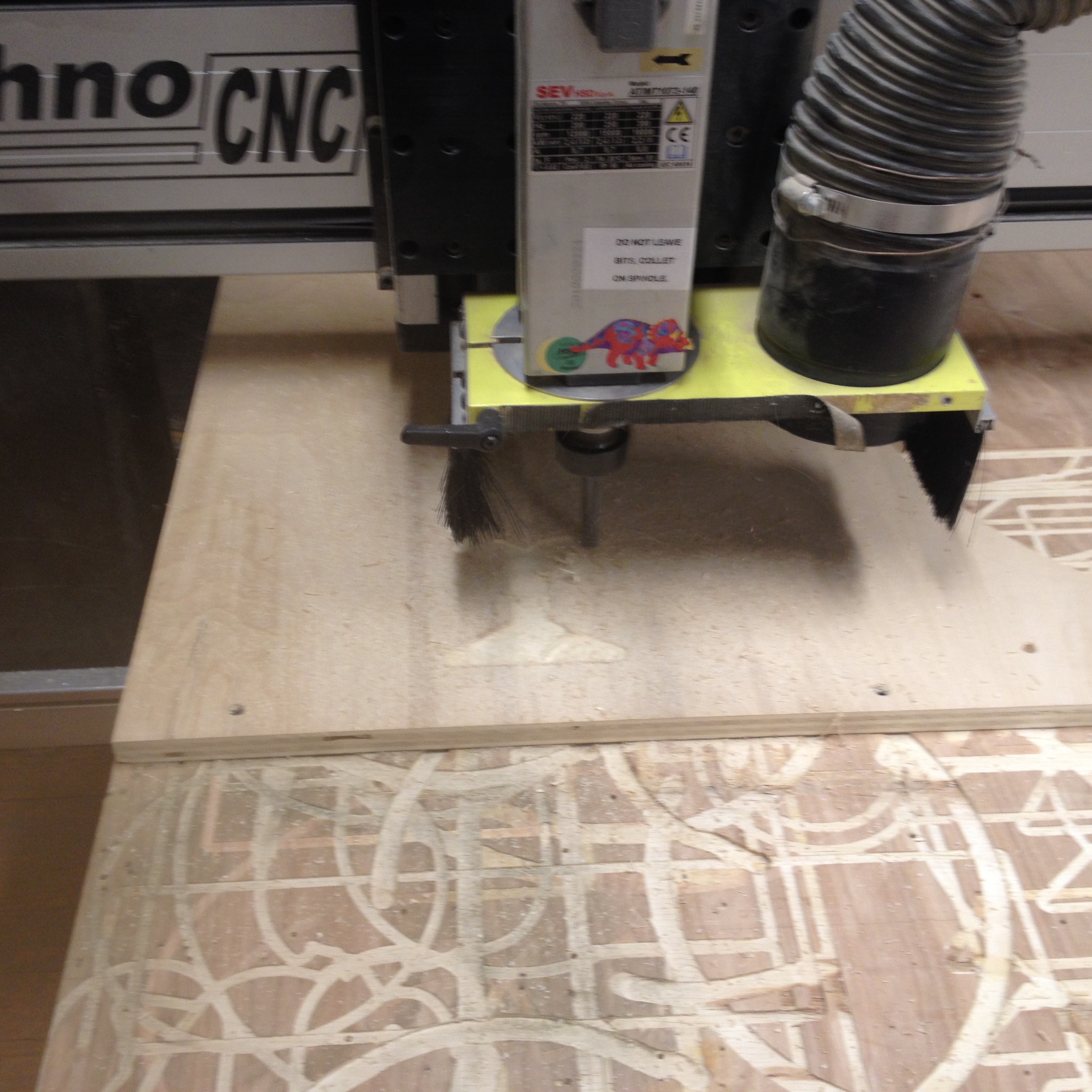
The Techno CNC is very dangerous, it has to be supervised while in operation, no exceptions.Vectorworks, paintbucket polygon tool is awesome. Must have a thumb drive for moving files to mastercam. Illustrator files can be imported in DXF.
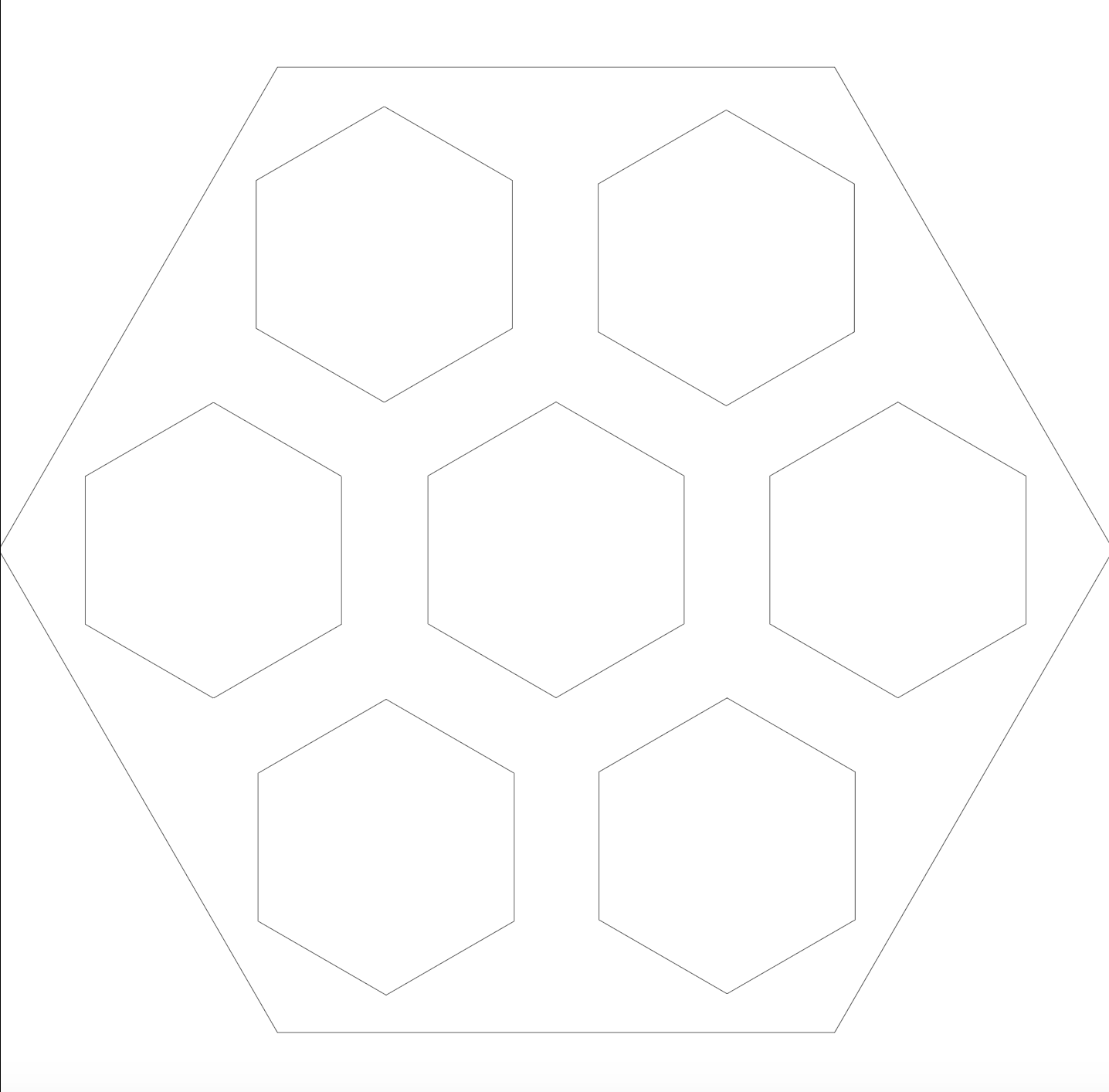
Techno CNC project:
This was my first attempt at a design for the CNC but I realized fairly quickly that it bogged down the Mastercam software and would have taken too long to machine.
I simplified the design quite a bit but still found it difficult to push through to the CNC.
The Version that worked was greatly simplified and optimized for the larger bit (broke my 1/4 inch against the material trying to zero the job).
Here is the beast at work.
The finished product:
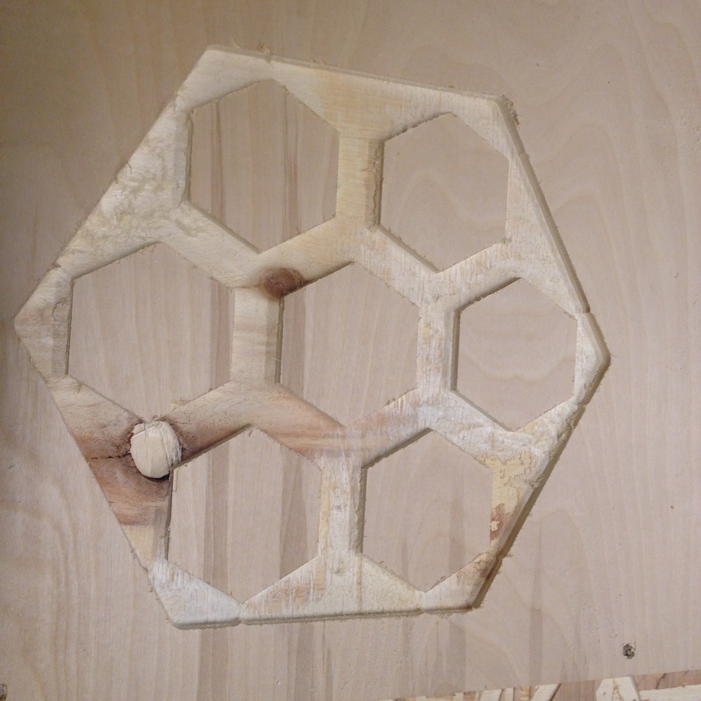
Turned out quite well in spite of having to carve through a rather unfortunate knot in the material. There was quite a bit of back and forth between the CAD, Mastercam, and CNC programs. Feel like I can get it to do what I want as long as I have a reason and the time to run the job.
Week 2:
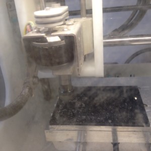
Othermill!
This was my first attempt at designing for the device but it turned out to be too fussy and geometrically sharp for the 1/8th inch bit. The shape is a phylogenetic tree (better suited for the laser cutter.

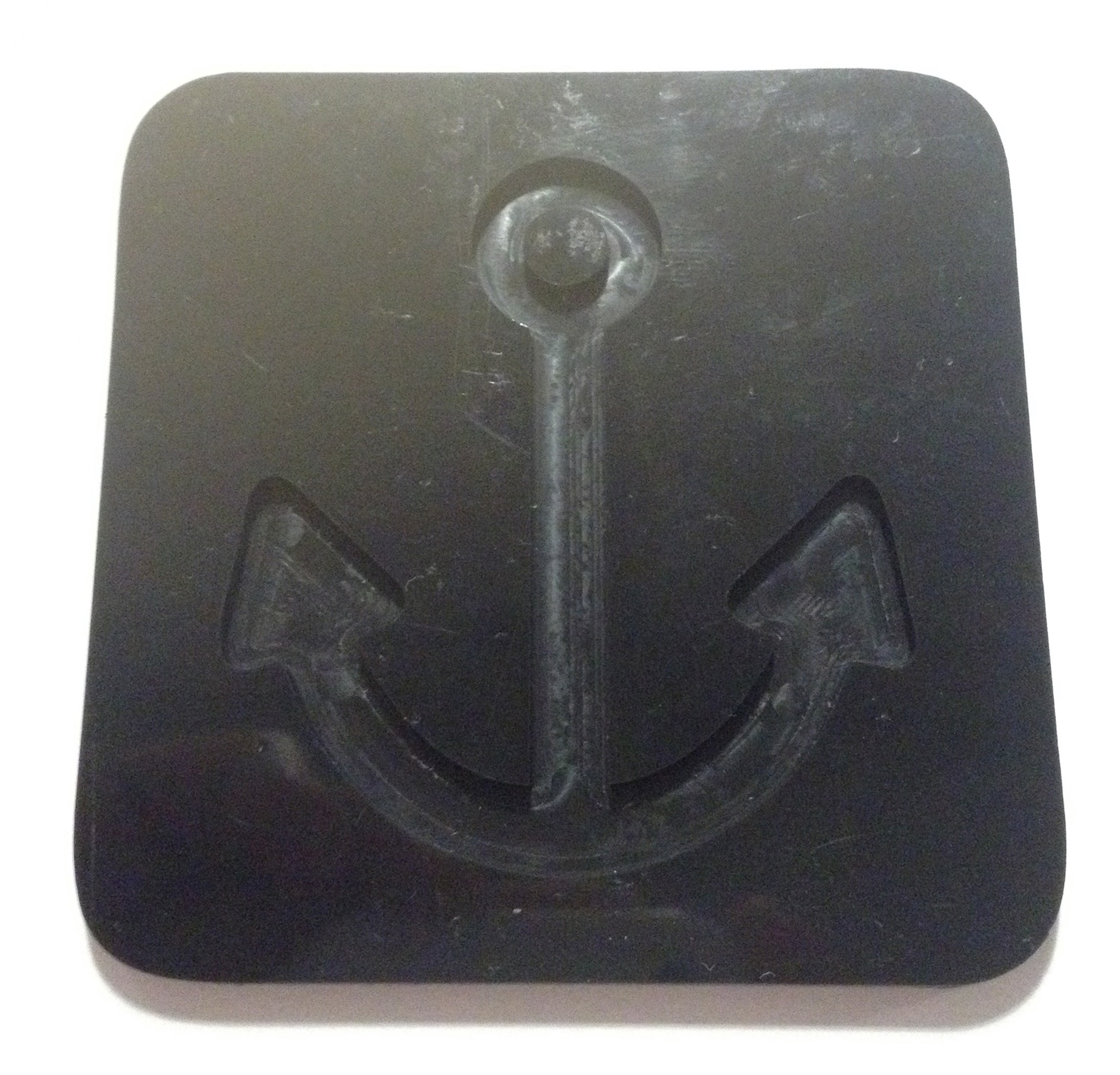
I chose something much more simple instead. A shape with rounded contours:

This made for a much better import into Otherplan:
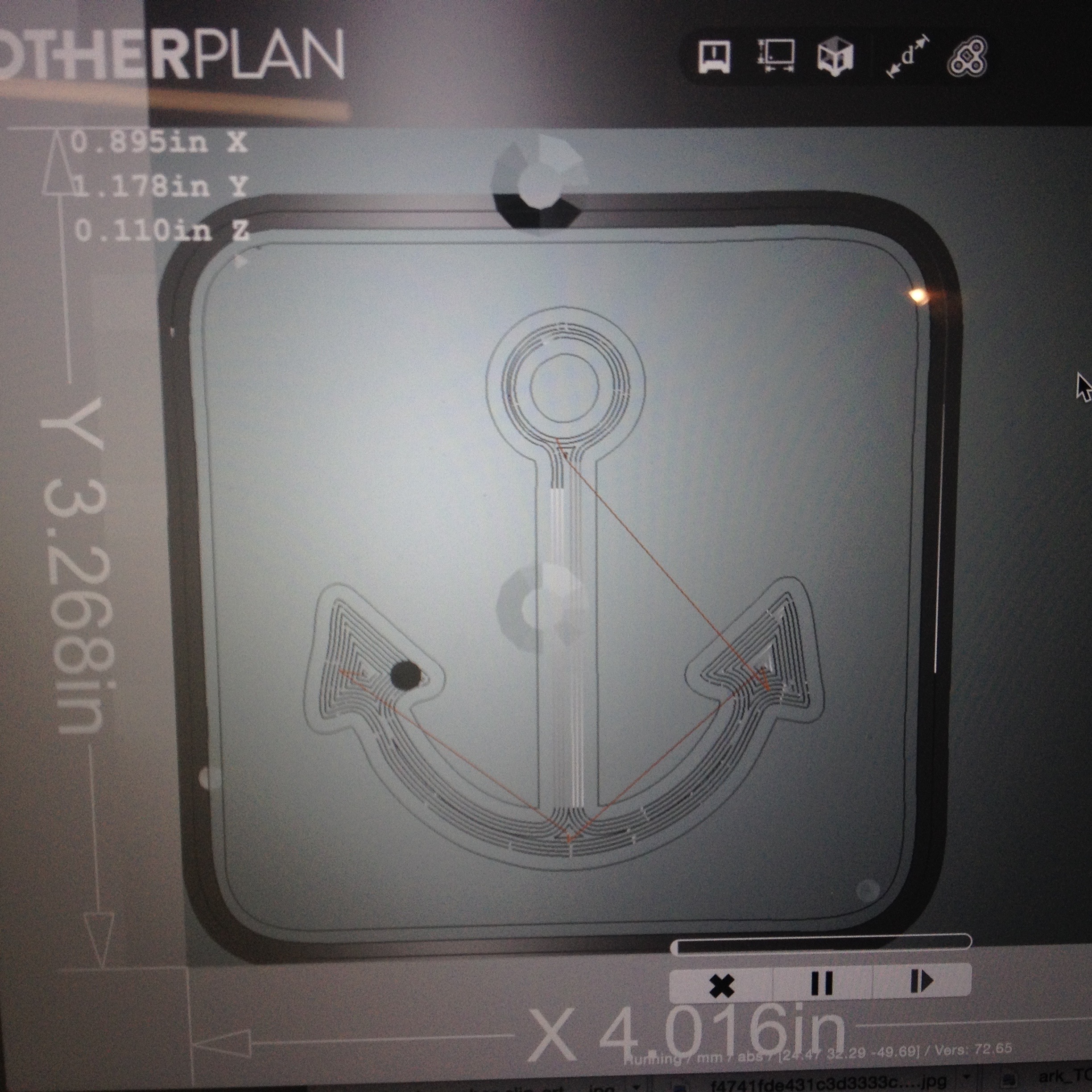
Starting the job:
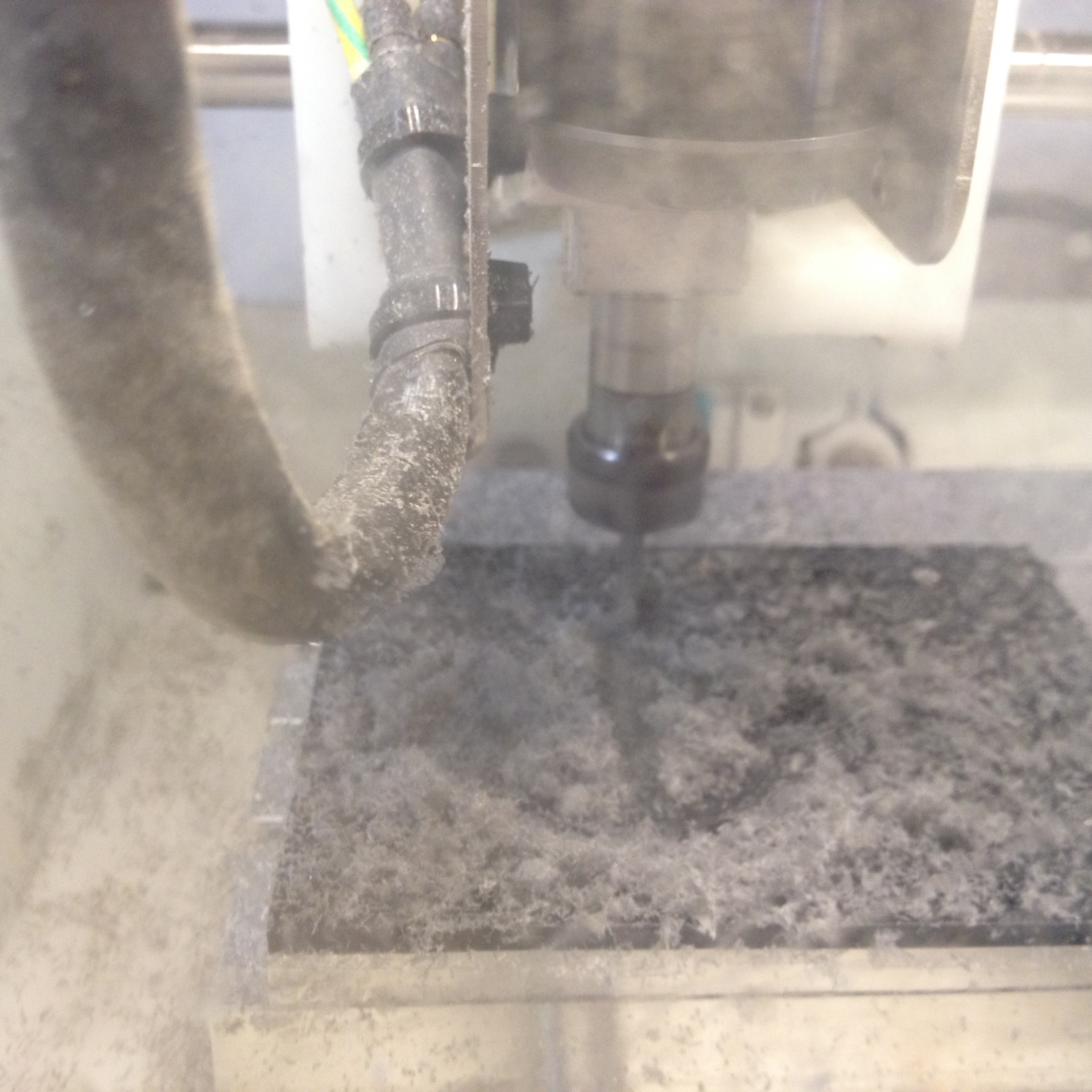
Midway:
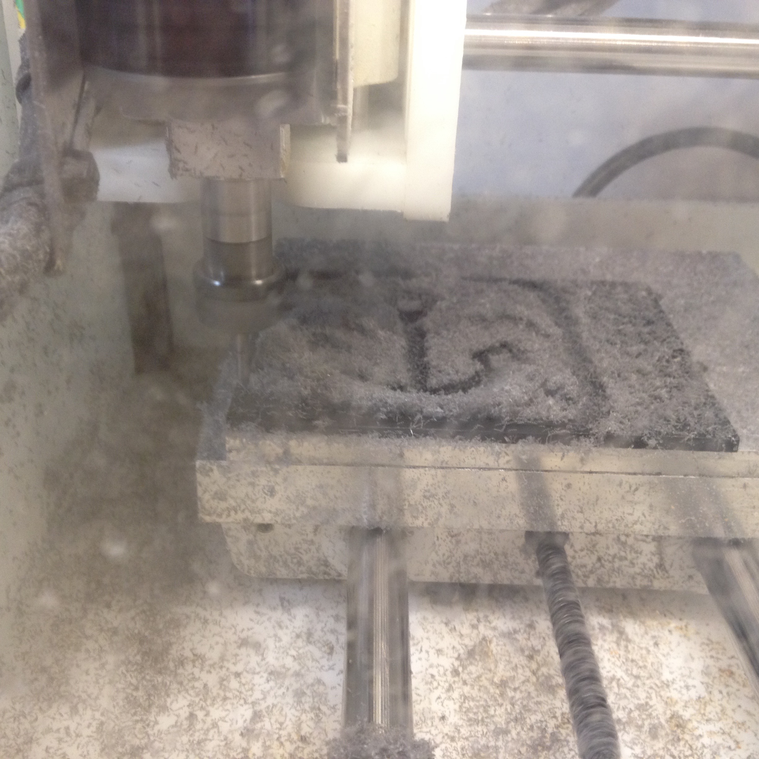
Finishing up:
End result:
Week 1:
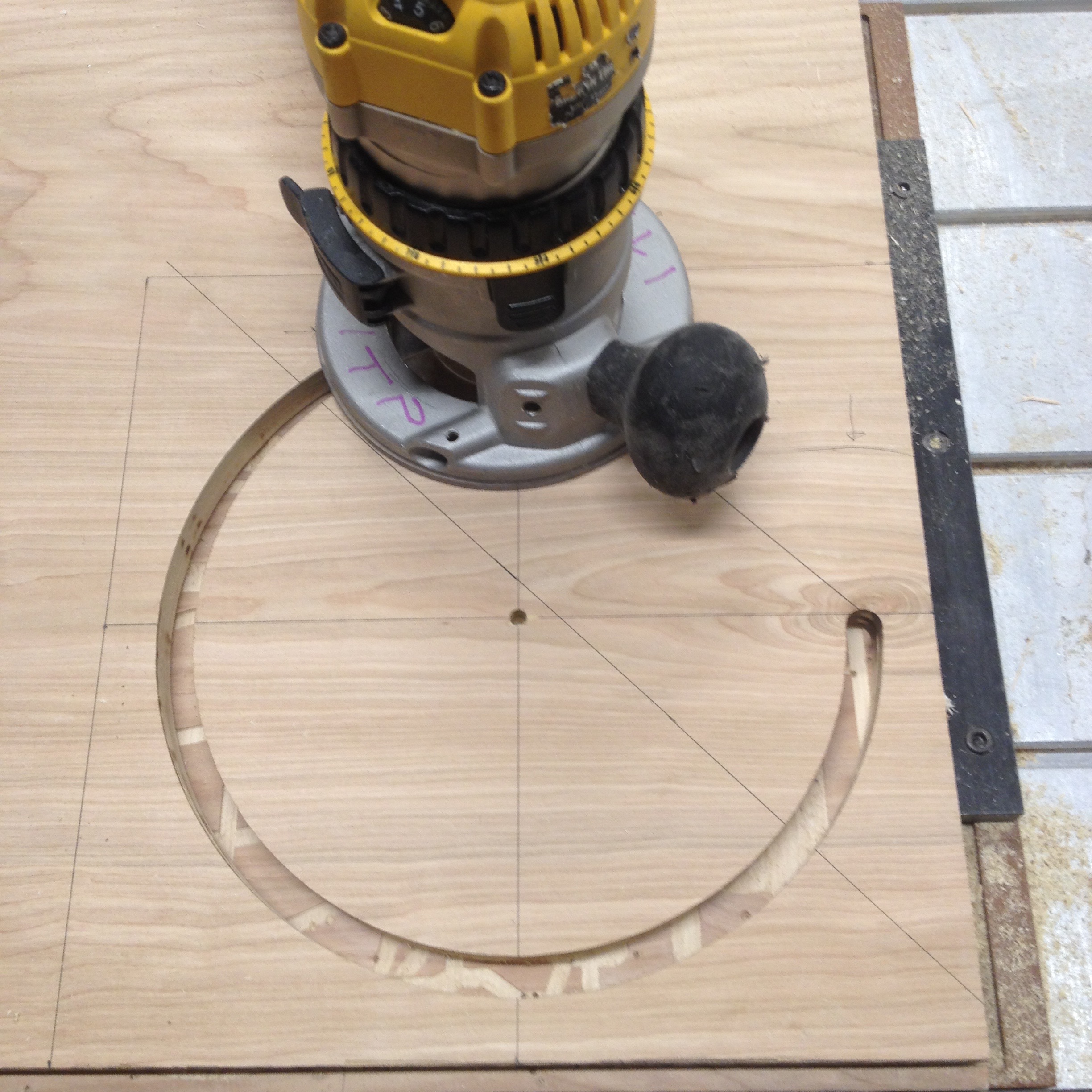
Measure twice…
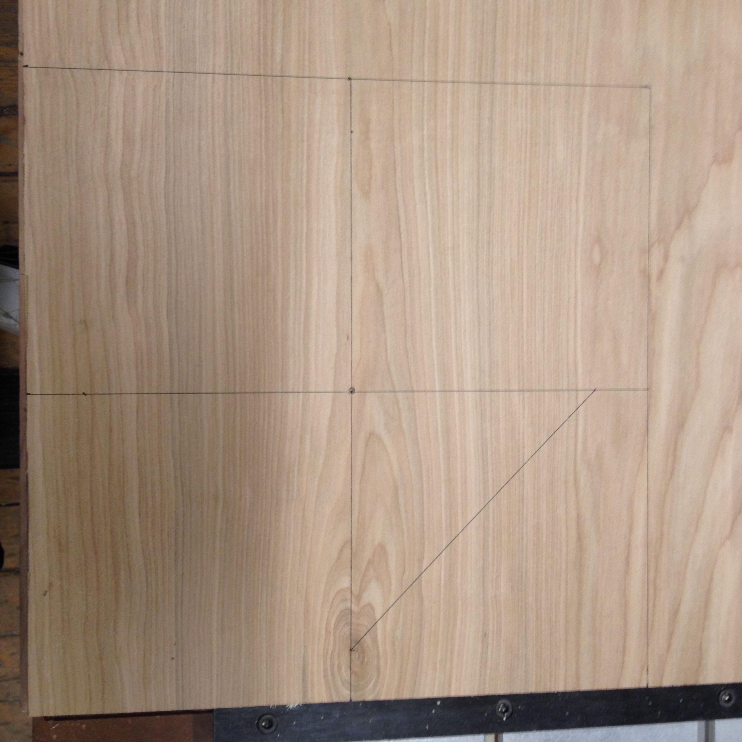 (I also measured and marked where the outside edge of the router should stop)
… and cut once …
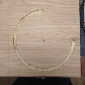
… twice …
… thrice …
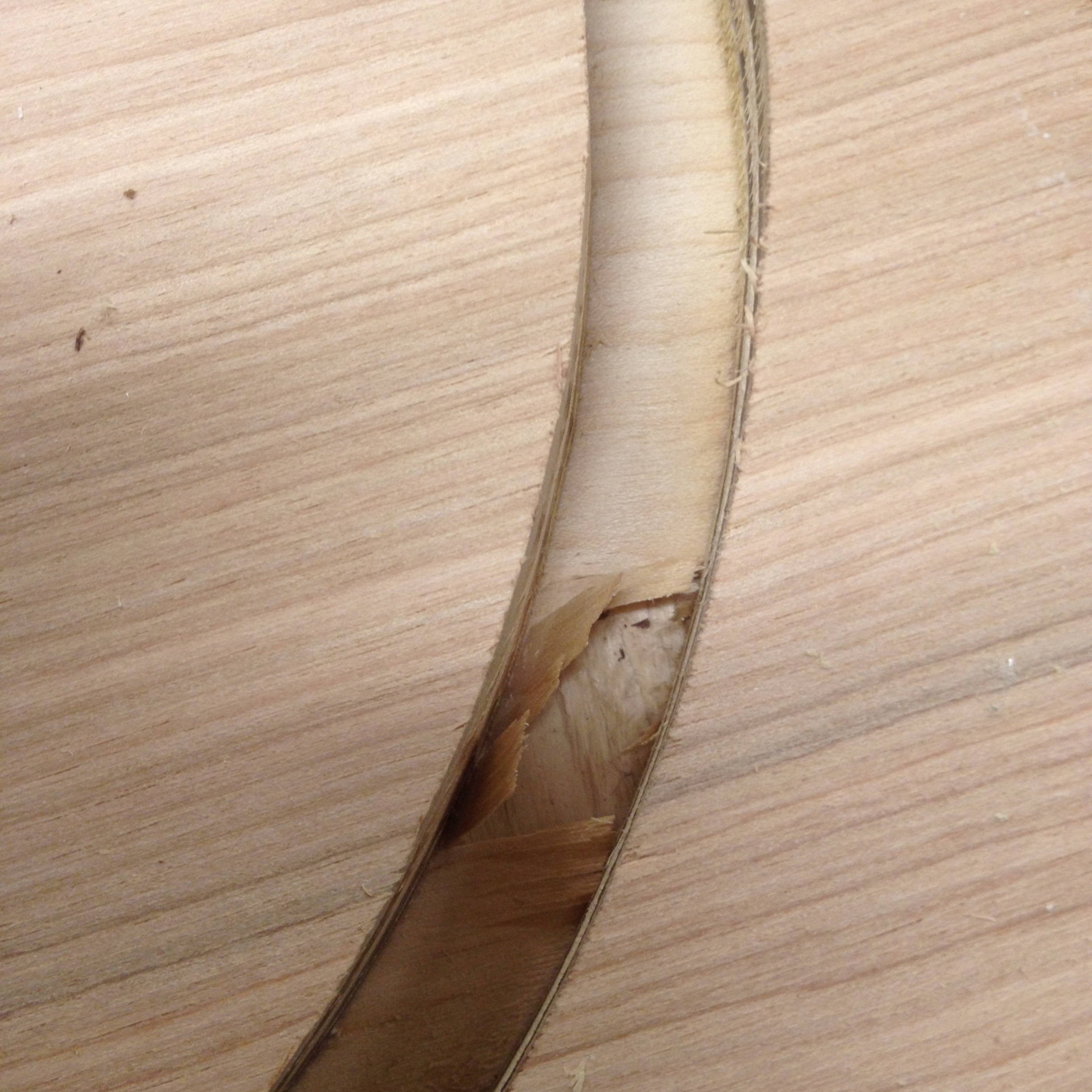
…four times? So close, it’s paper thin.
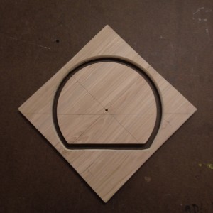
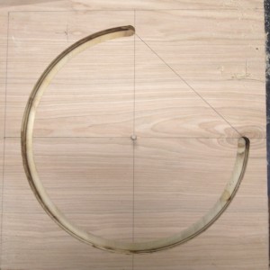
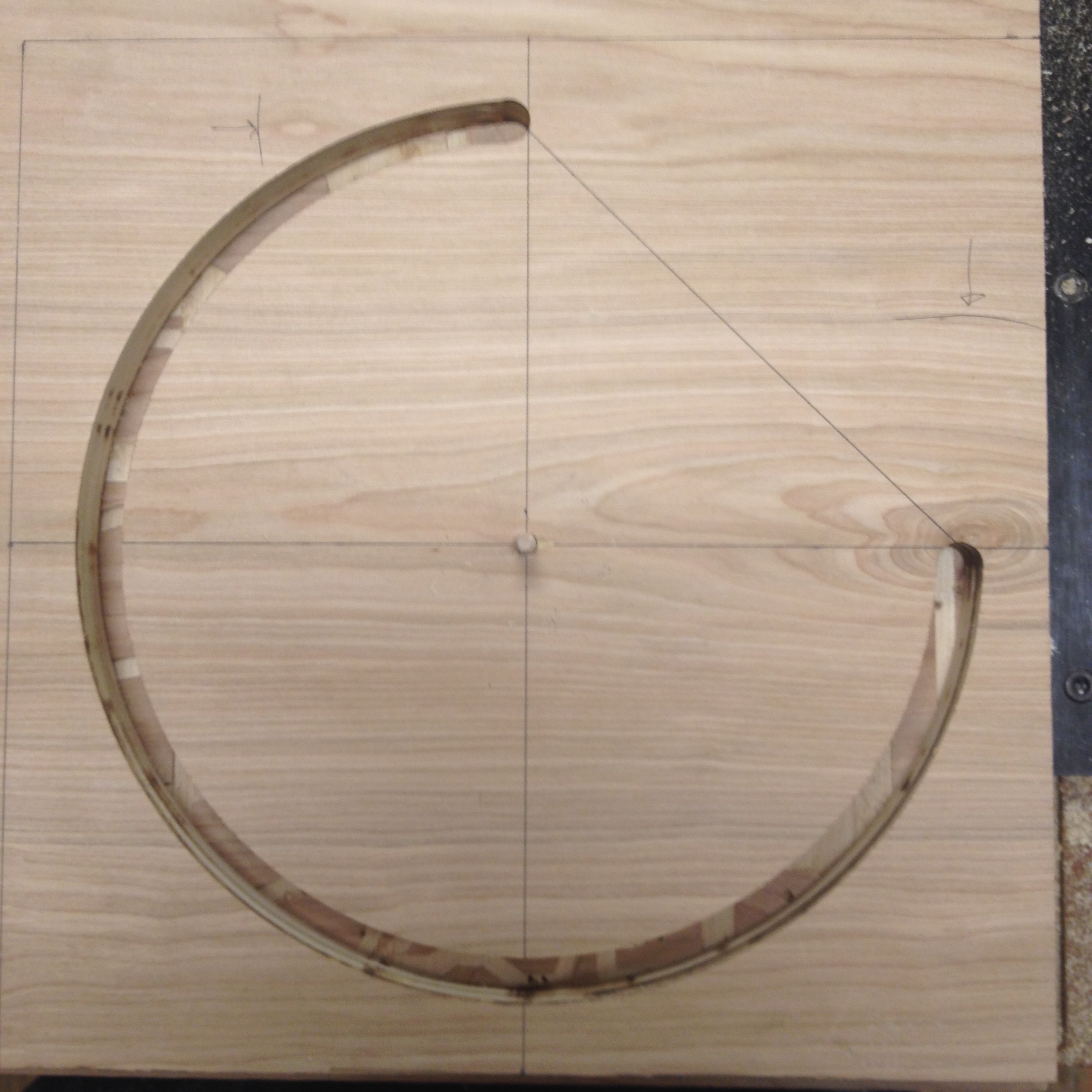
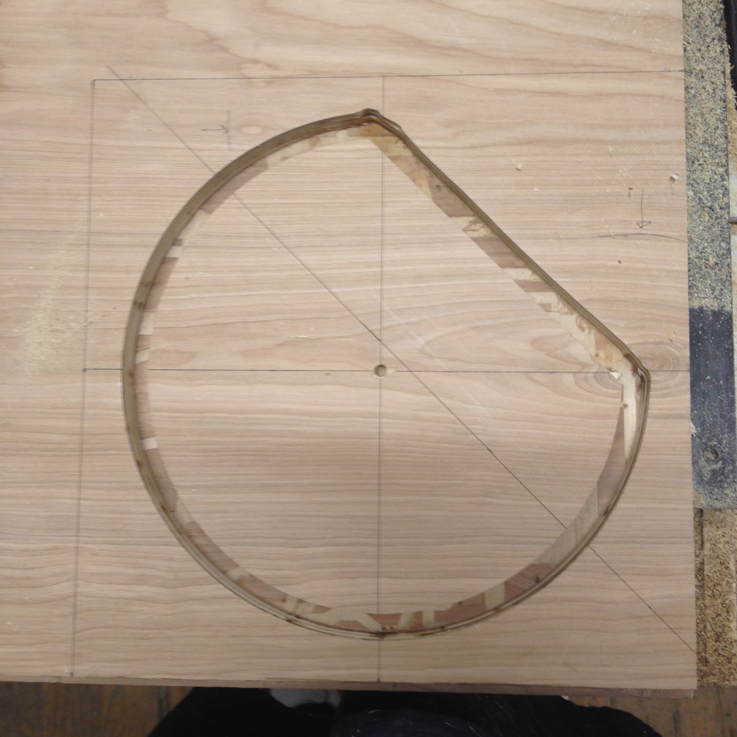
Last time around the block. Done with the 3/4 circle incision.
Measure for the outside edge path of the straight cut.
Clamp a straight edge.
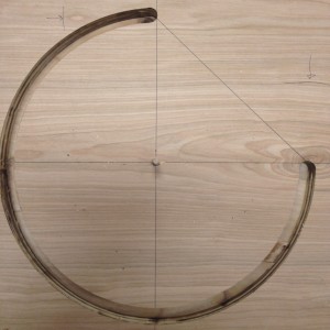
Three cuts later the excision is complete.
(A little biting on the corners)
Decided to try rounded router bit on the inside edge.
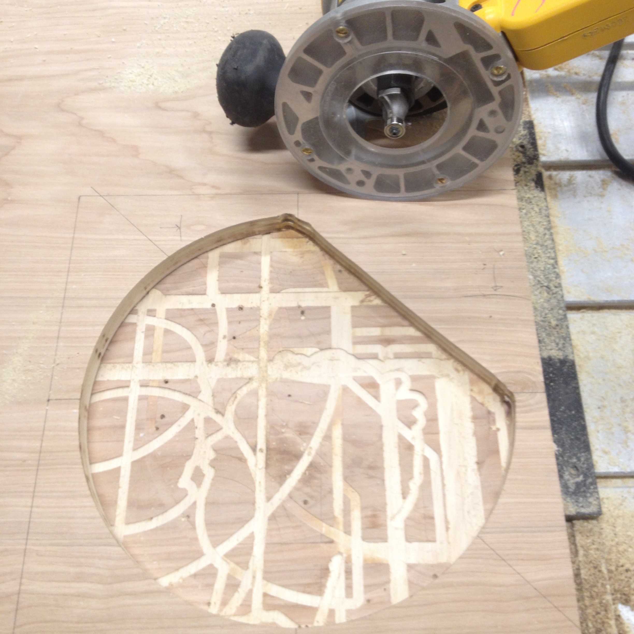
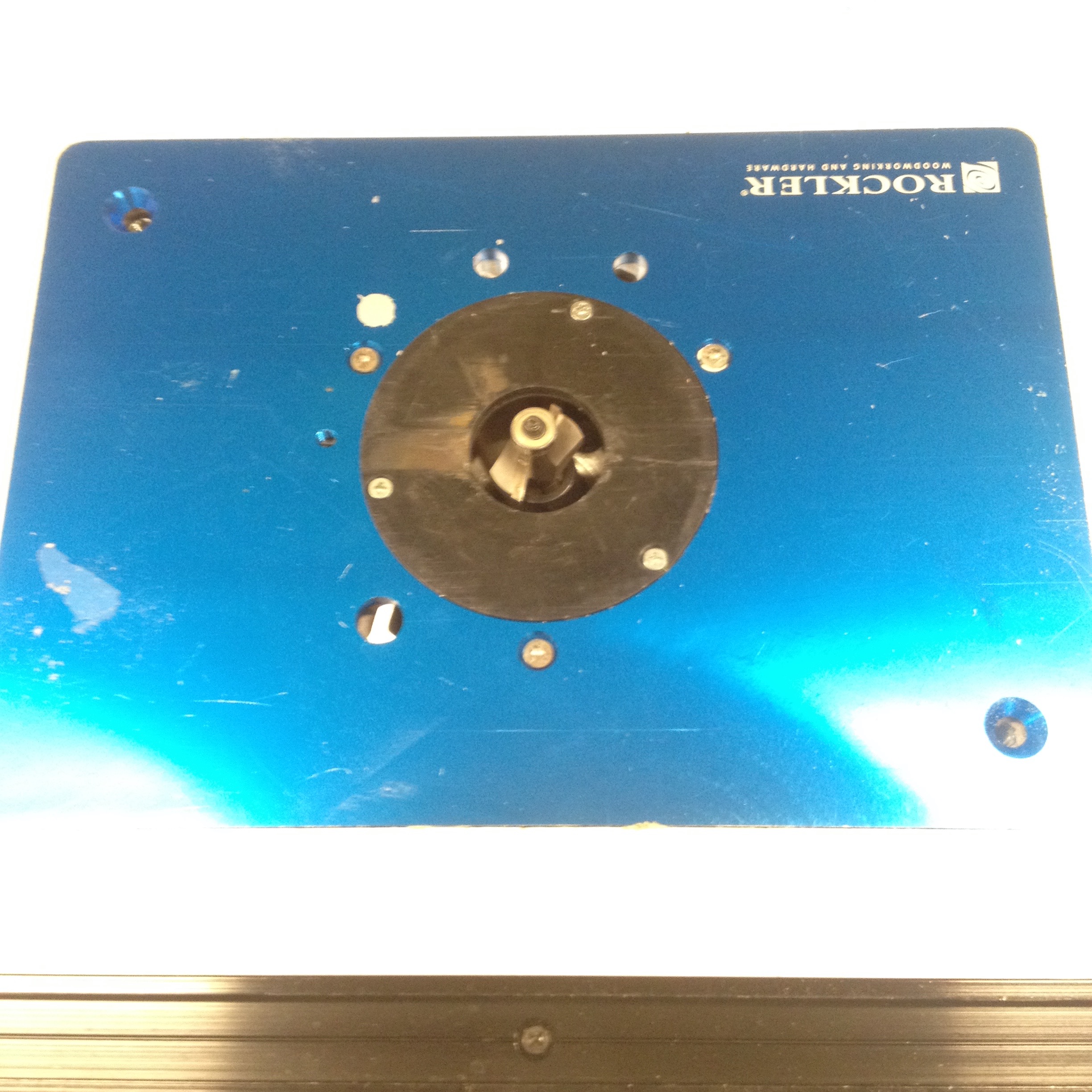
Also tried the router table setup.
A little sanding to prevent splinters and done.