
Introduction to Physical Computing
Instructor: Daniel Rozin
12/9/15
Final Project
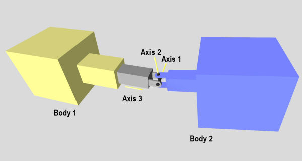
6 Axis Potentiometer Controller
The 6 -Axis Potentiometer Controller allows for rotation in 3 axes, and translation in 3 axes for complete freedom of movement in a zero gravity environment.
Th device consists of a three axis joystick, a two axis joystick, a single slide potentiometer, a fabricated housing, and a 3D printed controller ball. The three axis joystick allows the controller ball to rotate around it’s center point, the two axis controller captures movement forward, backward, left and right. The remaining axis (up and down) is captured by the slide potentiometer.
The internal, nestled acrylic housing restricts the linear motion of the assembly to the y axis (up and down) which is captured by the slide potentiometer.
The controller ball is designed to allow the user’s fingertips to rest in the divots, giving purchase for movement in all axes without repositioning the hand.
The data created is granular and analog, allowing for fine tuned, discrete movements instead of momentary, on – off movement.
The controller could find a use in zero gravity navigation, simulation training, and gaming.
With all axes of movement available, and adjustable; matching rotation, and position between orbiting bodies would be more intuitive and user friendly. In a sense, the controller acts as a miniature model of the spacecraft inside of the cockpit that can be used to fine tune the movement of the entire spacecraft.
Ideally even someone who is a stranger to the device and it’s purpose should be able to use it quickly and effectively with almost no training.
12/8/15
12/7/15
Coming together! Here the nested acrylic internal housing can be seen. It allows the slide potentiometer to capture up and down movement exclusive to other controller movements.
Connecting the wiring to the arduino board still has to be done but already all six analog inputs are ready to be used.
12/2/15
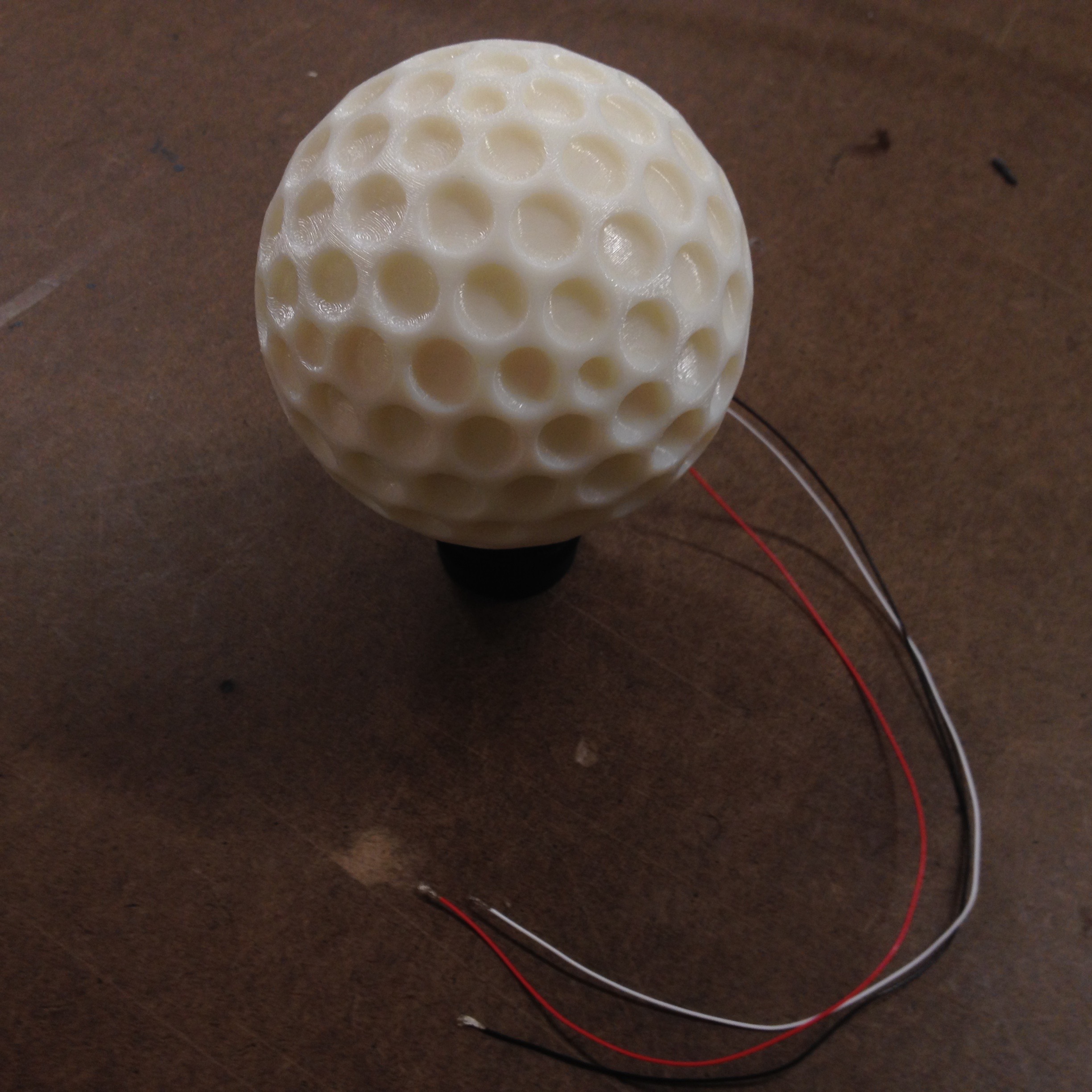
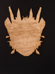
Here is the three axis joystick mounted inside the controller ball. I has a great hand feel, and is nicely centered for rotation.
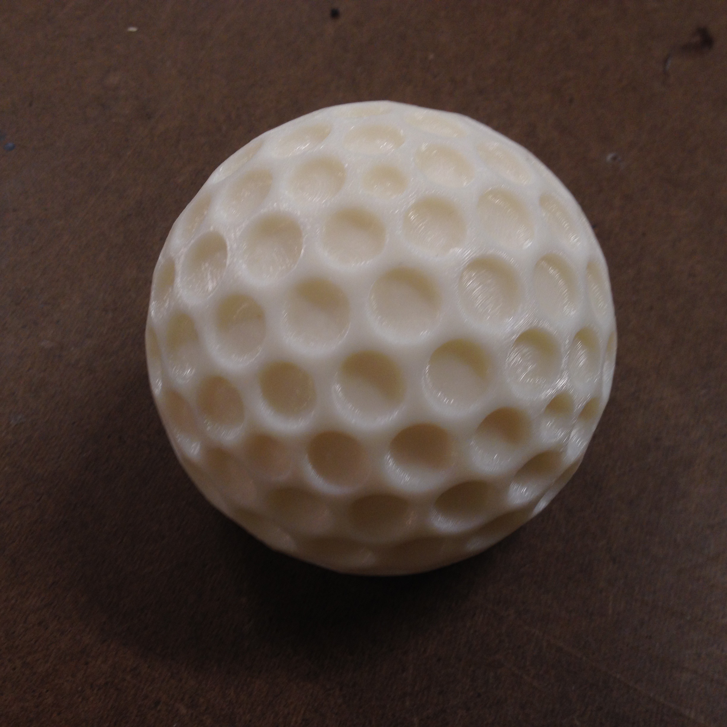
 This is the Laguardia Studio 3D print, much better quality.
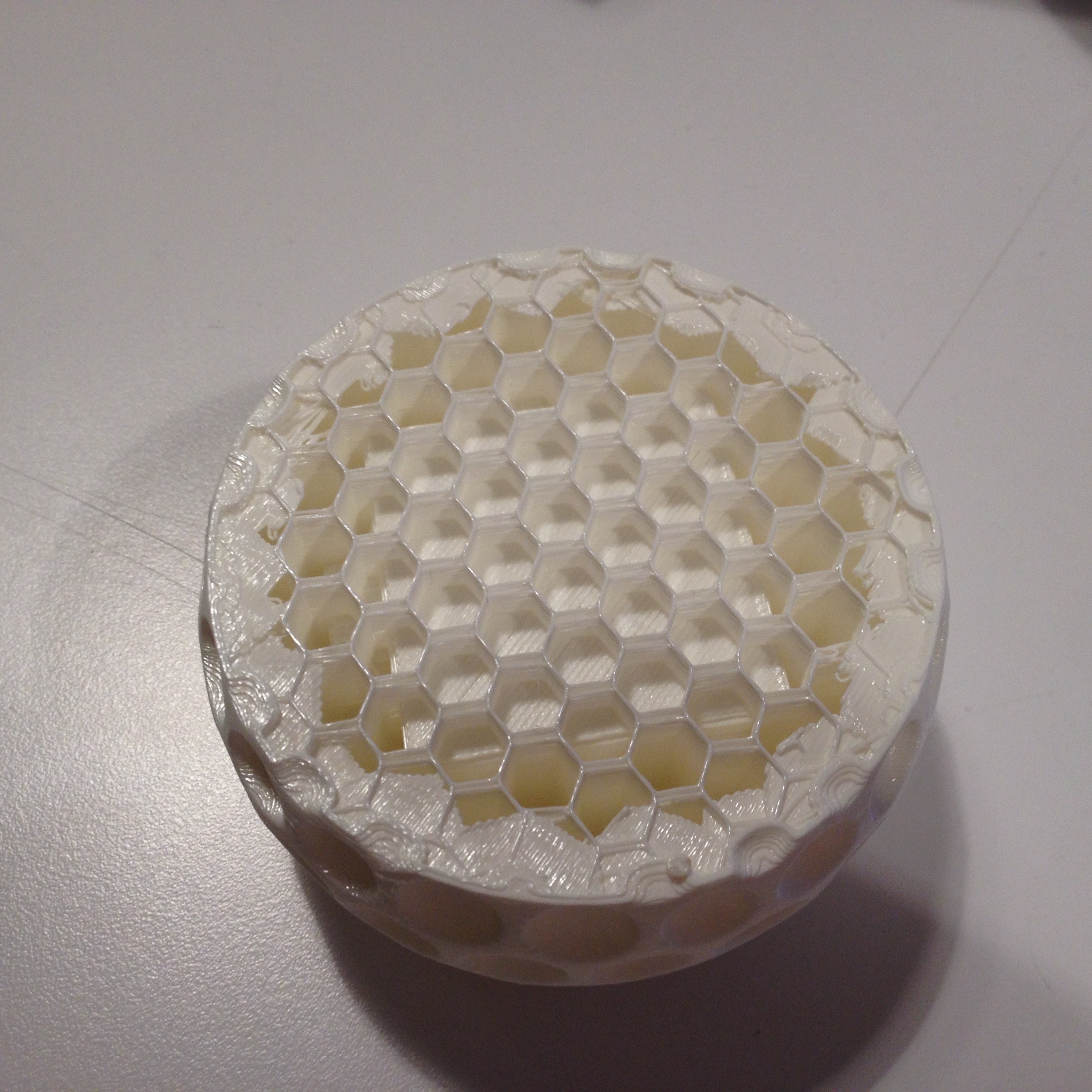
These are the two failed prints from the only functional makerbot on the floor.
Honestly it’s embarrassing that we only have one “functioning” 3D printer.
In user testing I fielded the now functional wireless gyroscopic controller ball.
11/18/15
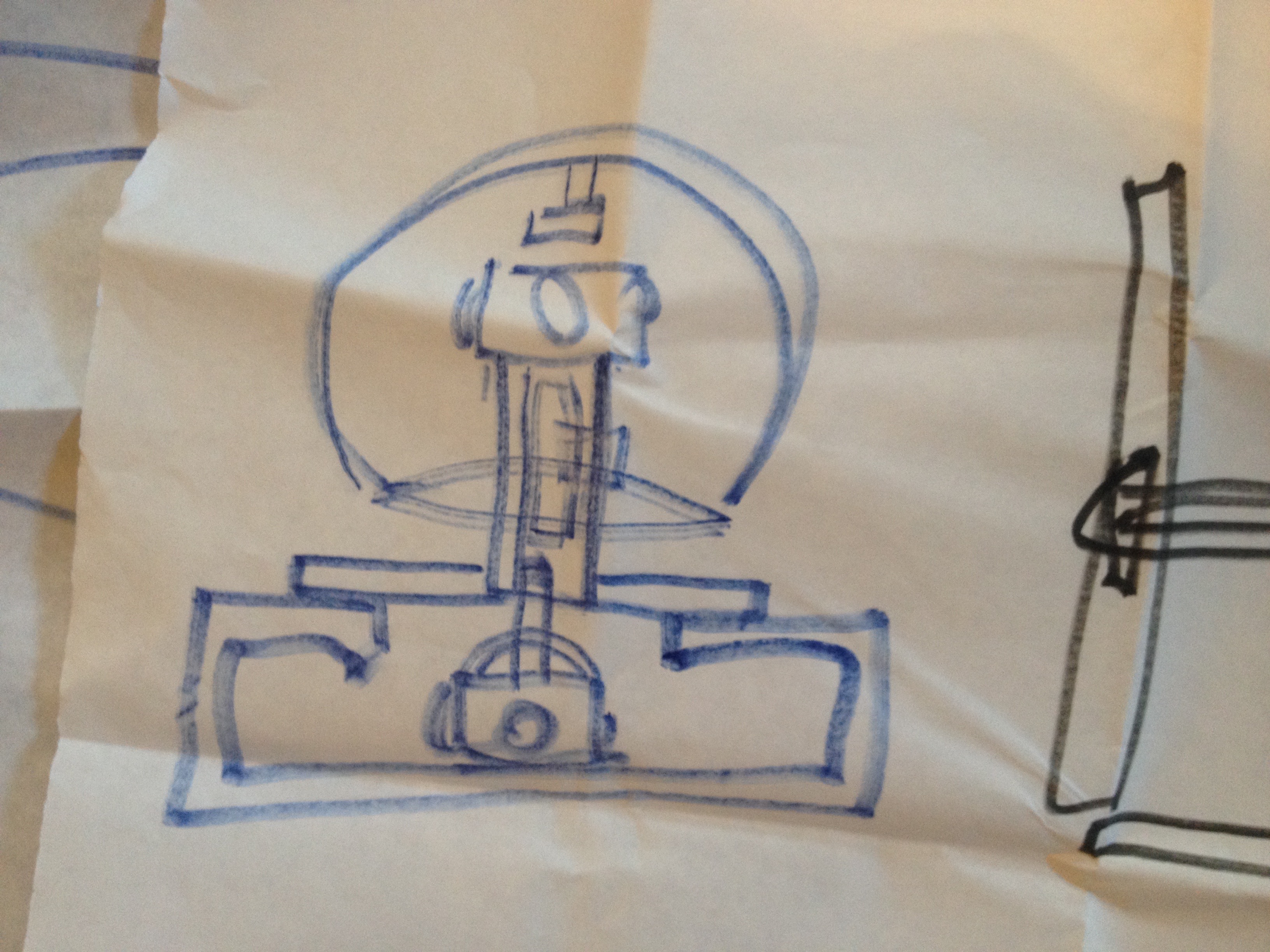
This is the setup I intend to implement for the controller build.
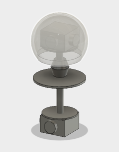
To preserve the Y axis spin I think this type of joint between the upper and lower controller would work.
11/15/15
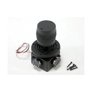
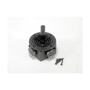
These arrived today:
3 axis controller:
2 axis controller:
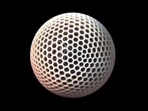
I’m thinking of using this kind of tactile textured for the controller sphere.
11/10/15
Here are some things that I discovered in the course of my research regarding 6 axis controllers.
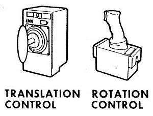
These are the primary tools used to navigate spacecraft:
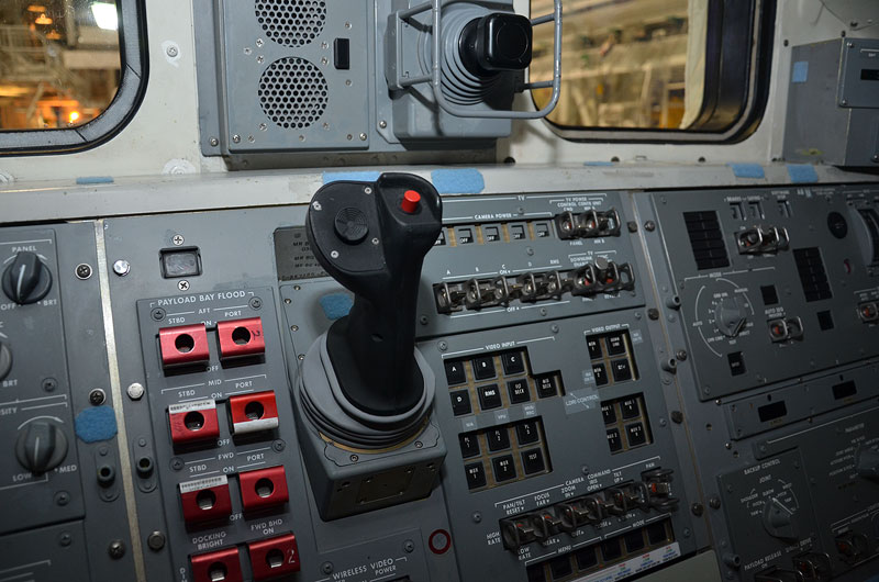
This is from the Dragon launch vehicle.
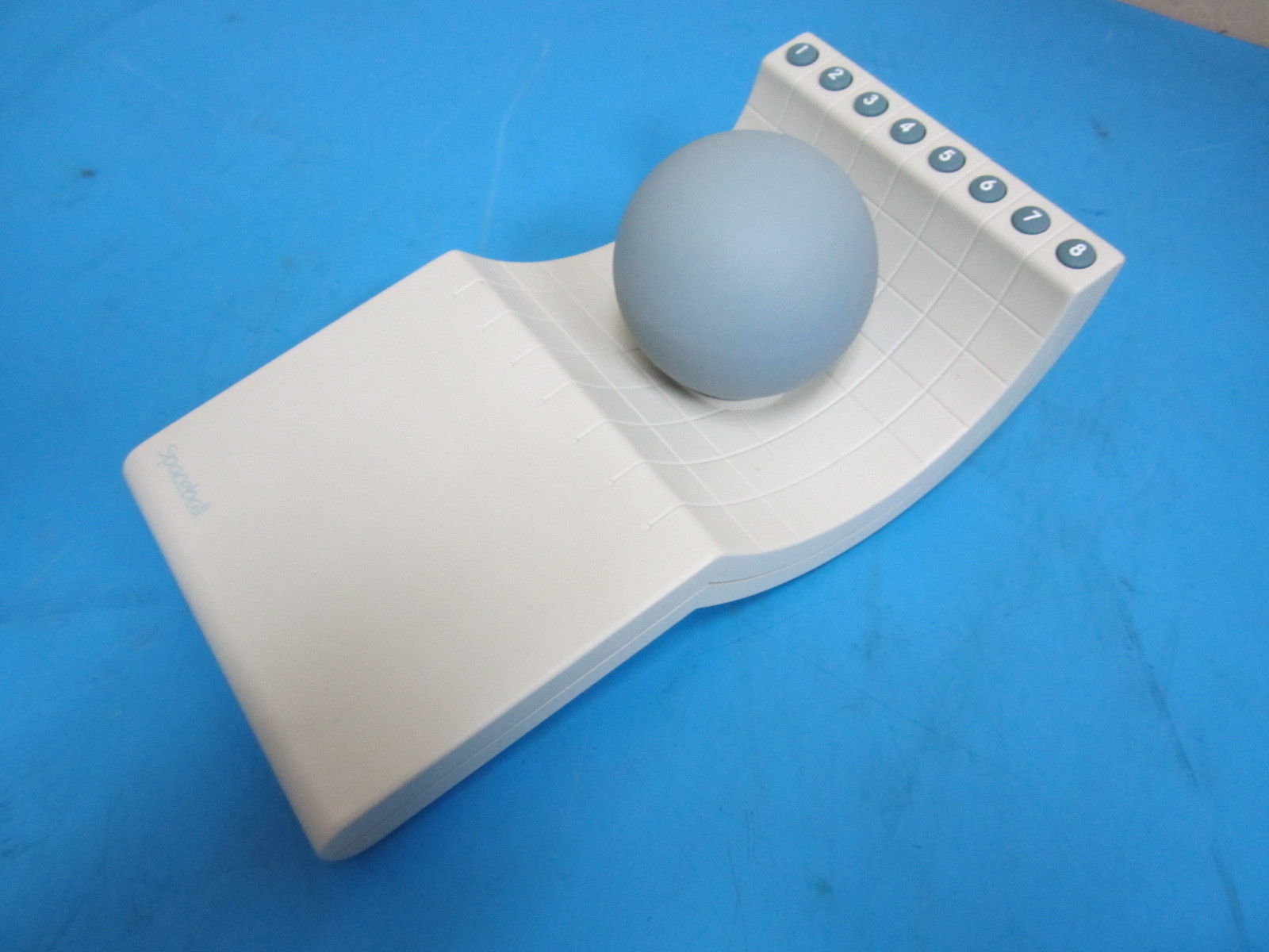
This is an early 6 axis controller for CAD programs
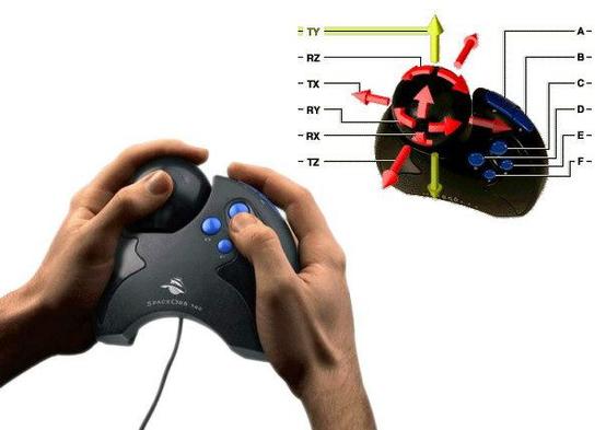
This 6 axis video game controller did not see widespread adoption
These are some ideas I have for fabricating a 6 axis controller. The first option is to use wireless gyroscopic and accelerometer data.
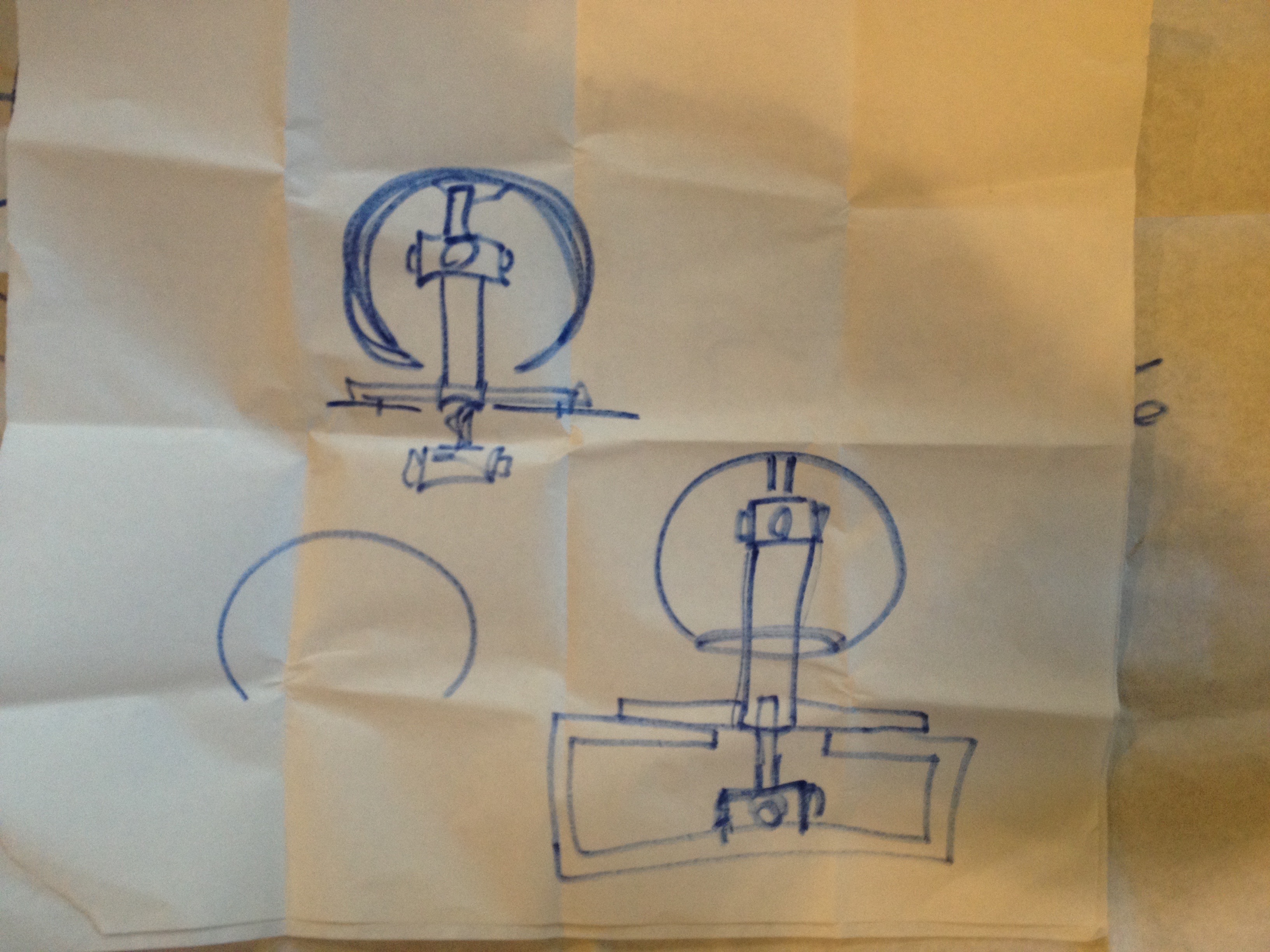
The second option is to use joysticks and potentiometers to make a hardwired controller.
One 2 axis controller in the top of the sphere for rotation, one underneath for translation. A slide potentiometer in the shaft for up and down. A 360 pot in the very top for spin in the Y axis.
Hoping for some guidance before I buy parts!
11/4/15
This is the playtesting “cardboard” version of the controller that I tested with several users during class.
The feedback was very useful and gave me a lot to think about. How quickly the user adapted to the controller depended on how much they knew about space exploration and the behavior of objects in zero gravity. Another factor was whether or not the user had experience with games, specifically flight simulators. One user who initially found the interaction counter intuitive warmed up to it when he declared that it was like “God-mode” (video game term for being able to fly around in a game instead of walking.
Some considerations/issues that I uncovered through the play testing:
Speed indication
Speed mapping (linear, exponential or logarithmic)
Thrust counteraction versus dampening
Should the device teach the user about how to navigate in space?
Display thruster activity
Display elements
11/2/15
So after some careful consideration I am currently proposing the following for my final project:
An intuitive navigation controller for 3D space.
I was thinking about space exploration and how clunky the controls are for maneuvering in the vacuum of space where there is no up or down and where there is no ocean of air to fly through. Specifically I was thinking about this scene in gravity:

Sandra Bullock’s character has to use two herky jerky jet controls to maneuver her awkward vessel into position to dock with the Chinese space station. The high drama of life and death is made all the more tense given the abstract, non-intuitive interface she has to contend with.
In a similar fashion there are not a lot of ideal ways to maneuver in virtual 3D space either. In most video games that take place in space the spacecraft fly around as if they are aircraft in earth’s atmosphere, banking turns, climbing nose up, etc.
3D software typically offers users the ability to navigate 3D space in the following manner with mouse and keyboard: pan up, left, right, down, zoom in and out, orbit around focal point.
Only a few purpose built tools exist to do the job more elegantly:
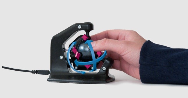
I have yet to test them out…

What I envision is a handheld, lightweight object that behaves like a model of the larger “ship” in 3D space, depending on the way it is moved it will either maintain a neutral position, maintain movement in any direction or accelerate in any direction. The controller will have a neutral position as well as a maintain speed position range, and an accelerate range. I think color coding them would work well.
Final Project Plan:
I plan to pair the device with a large screen running a 3D environment to be navigated by users/testers. The device will consist of a sensor embedded platform with a spherical controller that can be moved over it.
I plan to test it for intuitiveness and durability with a variety of users over the course of the project build and refinement.
Timeline:
Week 11
Primary Fabrication
Week 12
Sensor and software integration
Week 13
Durability and user testing
Week 14
Final Iteration ready for show
Initial BOM:
3 – Plexiglass sheets 3 ft X 3ft
1 – Sphere controller shell (preformed styrofoam or 3D printed)
1 – Speaker
1 – Big screen TV
1 – LED strip light roll
1 – gyroscopic sensor
? – proximity sensors?
10/27/15
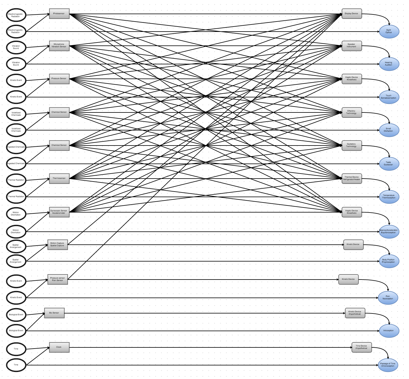
In the search for an idea for my PCOMP final project I decided to make a visual map. This map shows how human senses and machine sensors can potentially interact. It starts with physical phenomena that is split into two ranges; the range that is within human detection/tolerance, and the range within machine detection/tolerance (a much larger range).
In most cases the machine range of sensor input has a corresponding range of output. The input to a machine sensor can be processed and output via other devices so that a human may take in information that would otherwise be outside the normal, human range. For example, a sound that is too faint to be heard can be recorded with a microphone, adjusted to fall within the range of human hearing and output to a speaker so that it may be experienced as sound.
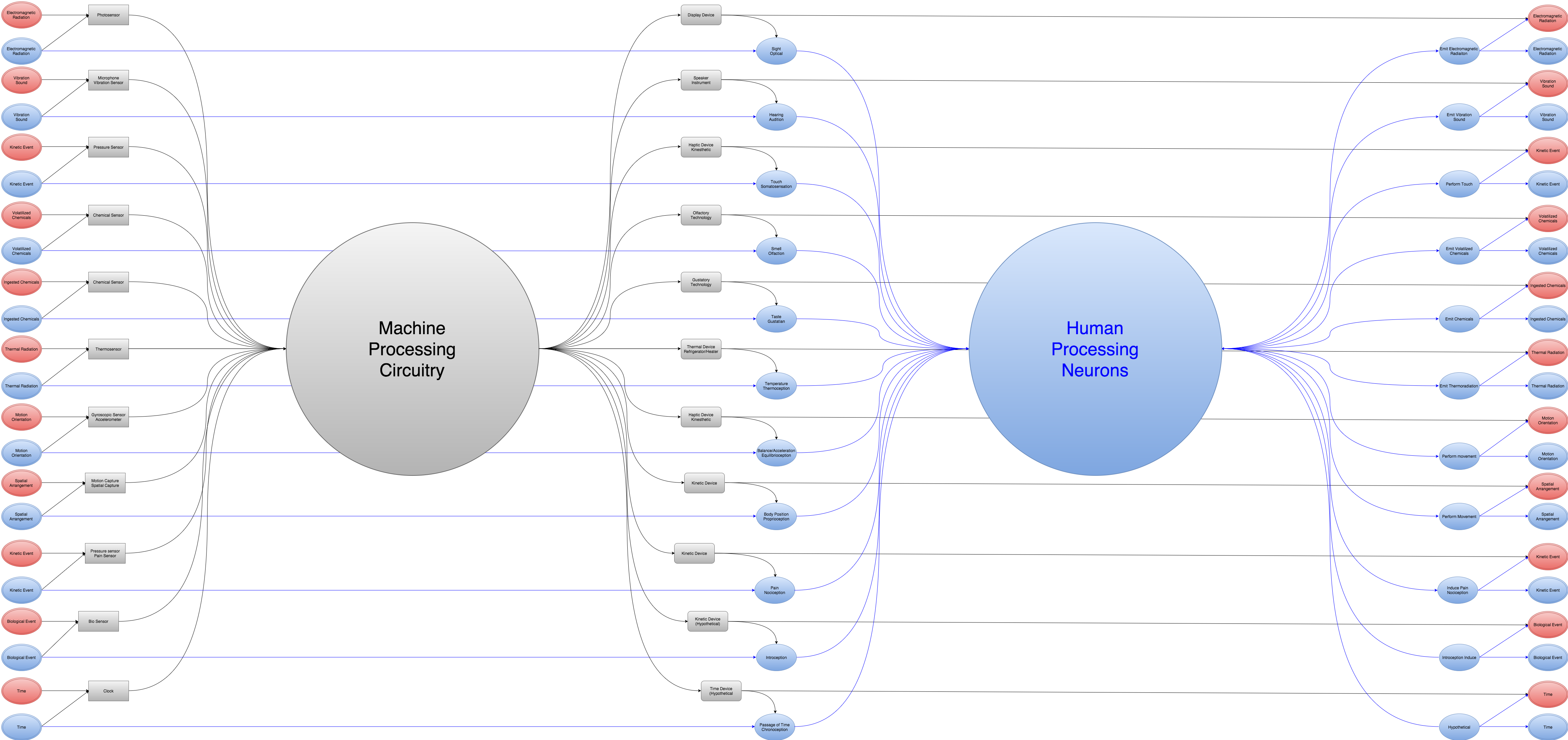
Below is an earlier version of the map that started to get too dense graphically.
I have two ideas for morphable fabric. One made up of lycra, and a sandwiched rubber mesh layer with crisscrossing muscle wires. The other would one would be a little more simple but use micro actuators to change color/texture by flipping over scale like pieces.
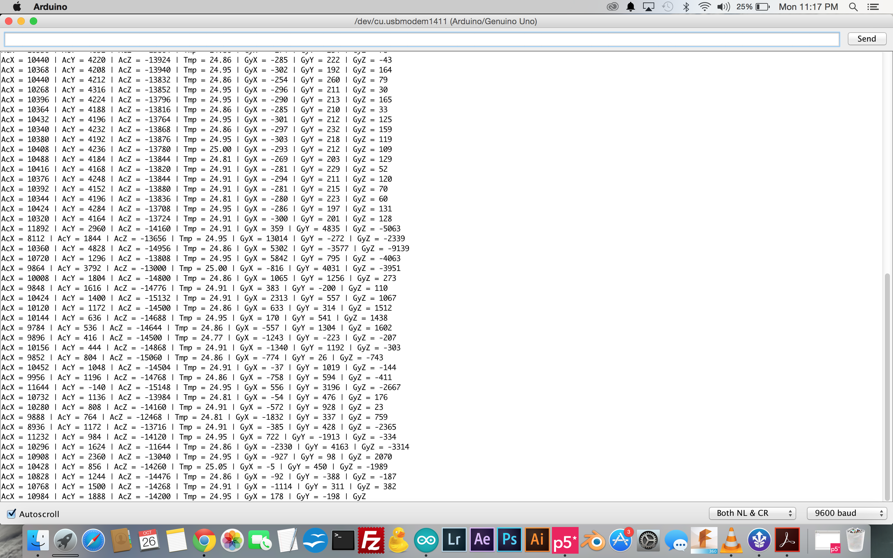
11/27/15
After some work with the gyroscopic sensor I now have a serial output that includes complete rotation coming from the Arduino uno. The next step is to get the new strings of values to work with the P5 sketch, and connect the gyro sensor to the light blue bean.
10/25/15
Doing some Mid Term post mortem. I was very happy with the P5 graphics, with the exception of the seam on the globe. I was less satisfied with the lack of a 1 – 1 match between the orientation of the globe controller and the globe. I am going to attempt to fix this now that my gyroscopic sensor has arrived.
Feedback from the other students in the class has been very positive. Lots of compliments. Criticisms were largely centered around orientation matching problem. Ideas for improvement were to increase the range of functionality to include movement and scaling.
Once I get the gyroscopic sensor information working with the sketch I’ll see what else I can add to the interactivity.
10/21/15
Mid Term Project:
Interactive Wireless Globe Controller
A Light Blue Bean board with battery is mounted inside a styrofoam sphere. The accelerometer drives a P5 Sketch of a 3D globe with realistic earth texture map and starfield background. The interaction is not aligned as I would like due to the limitations of the data generated by the accelerometer sensor. I have ordered a gyroscope sensor that will hopefully get it to a 1 -1 rotation.
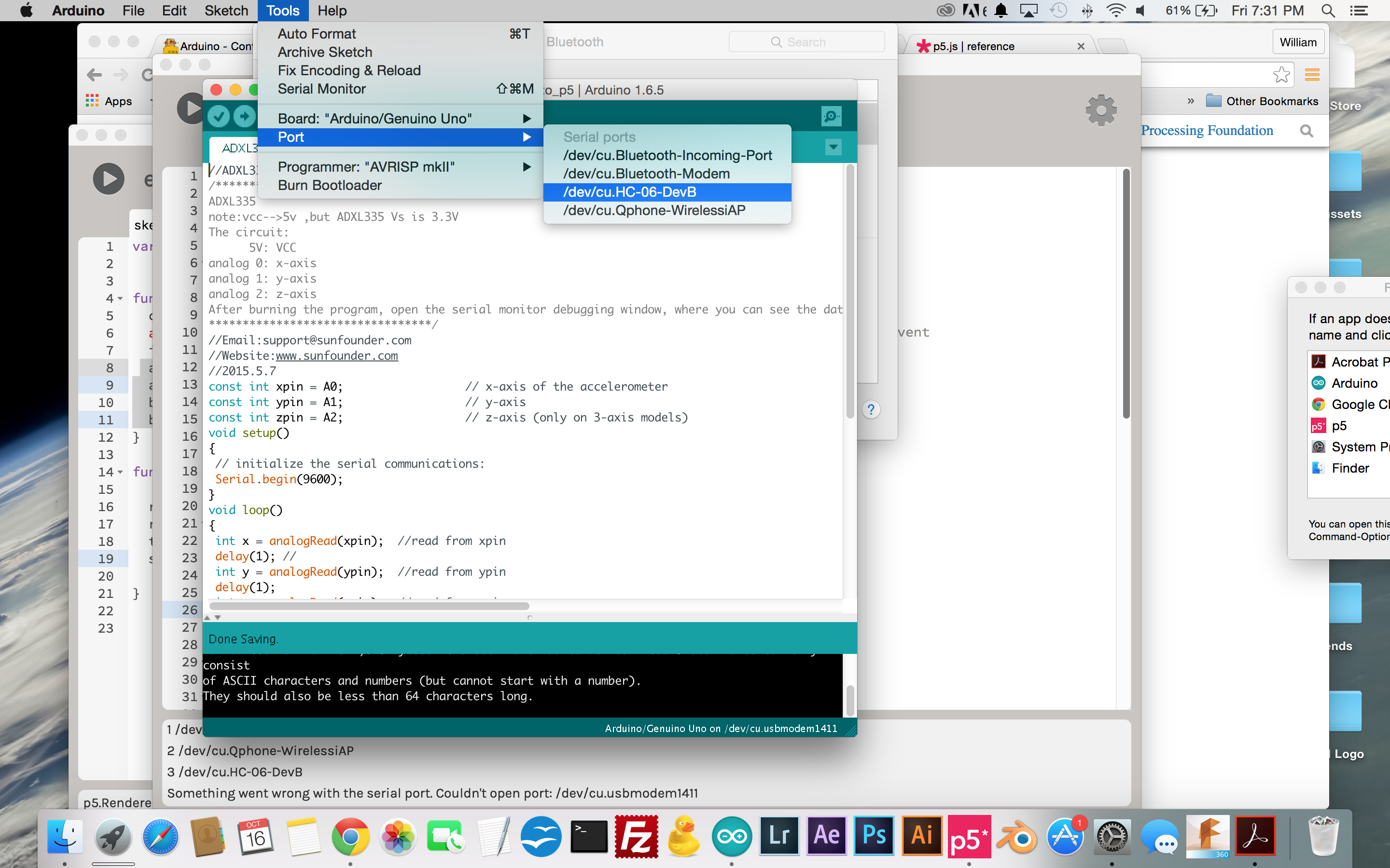
10/20/15
The bluetooth module for my arduino board refused to submit to my persistent fiddling. My buddy Sam saveed me from frustration by letting me borrow his Light Blue Bean Arduino.
10/20/15
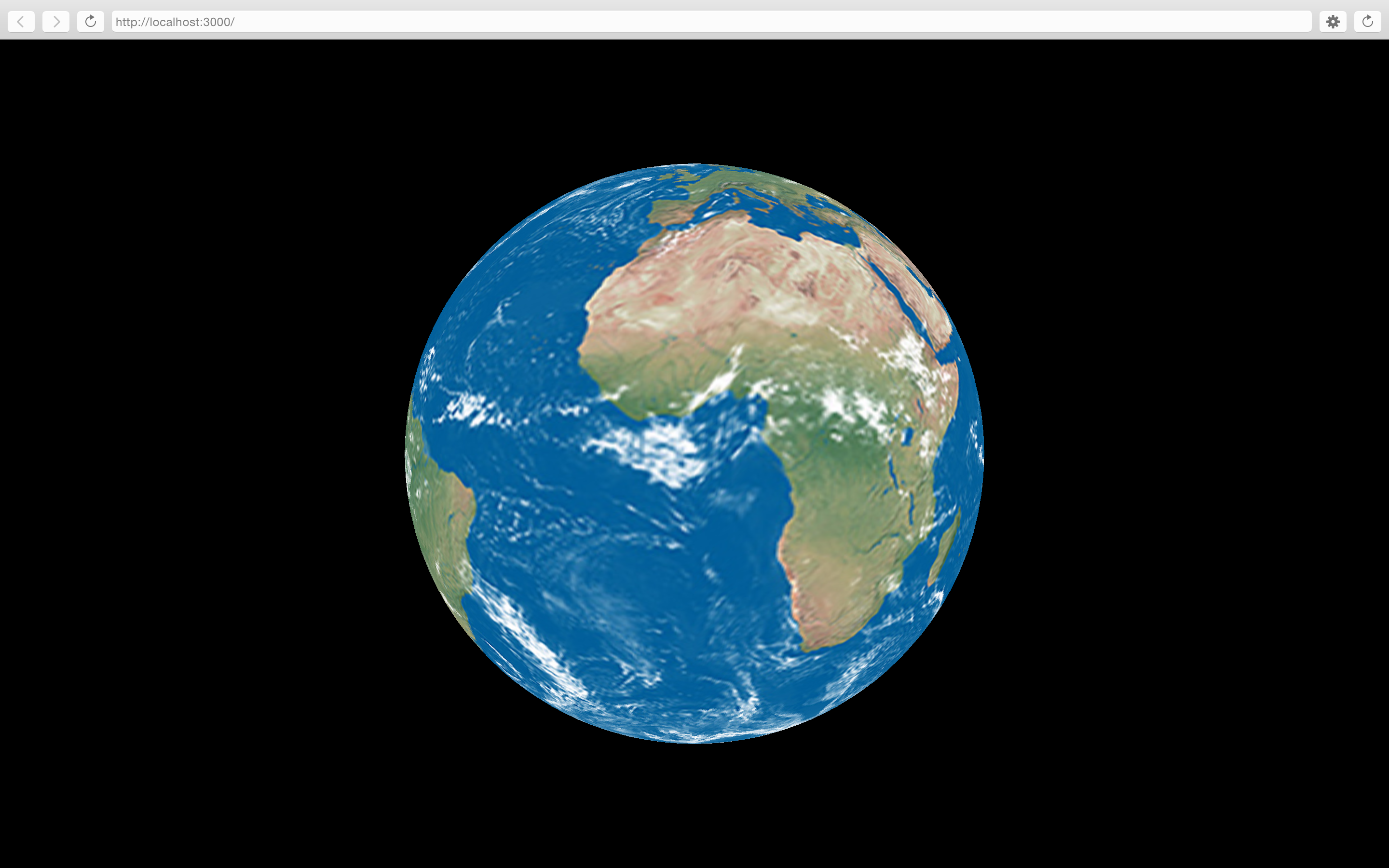
After banging my head against the wall of an uncooperative bluetooth module for my arduino board my buddy Sam let me borrow his Light Blue Bean board. The board connected with minimal tweaking, and I was able to get the data from the accelerometer to run my 3D P5 sketch wirelessly. With the board mounted in the center of a styrofoam sphere there is a pleasingly non-keyboard, non-mouse, non-touchscreen interaction. The P5 sketch makes use of the recently added WEBGL features in P5. The earth from space texture map is from NASA. The starfield is mapped to a large cube moved back into z space.
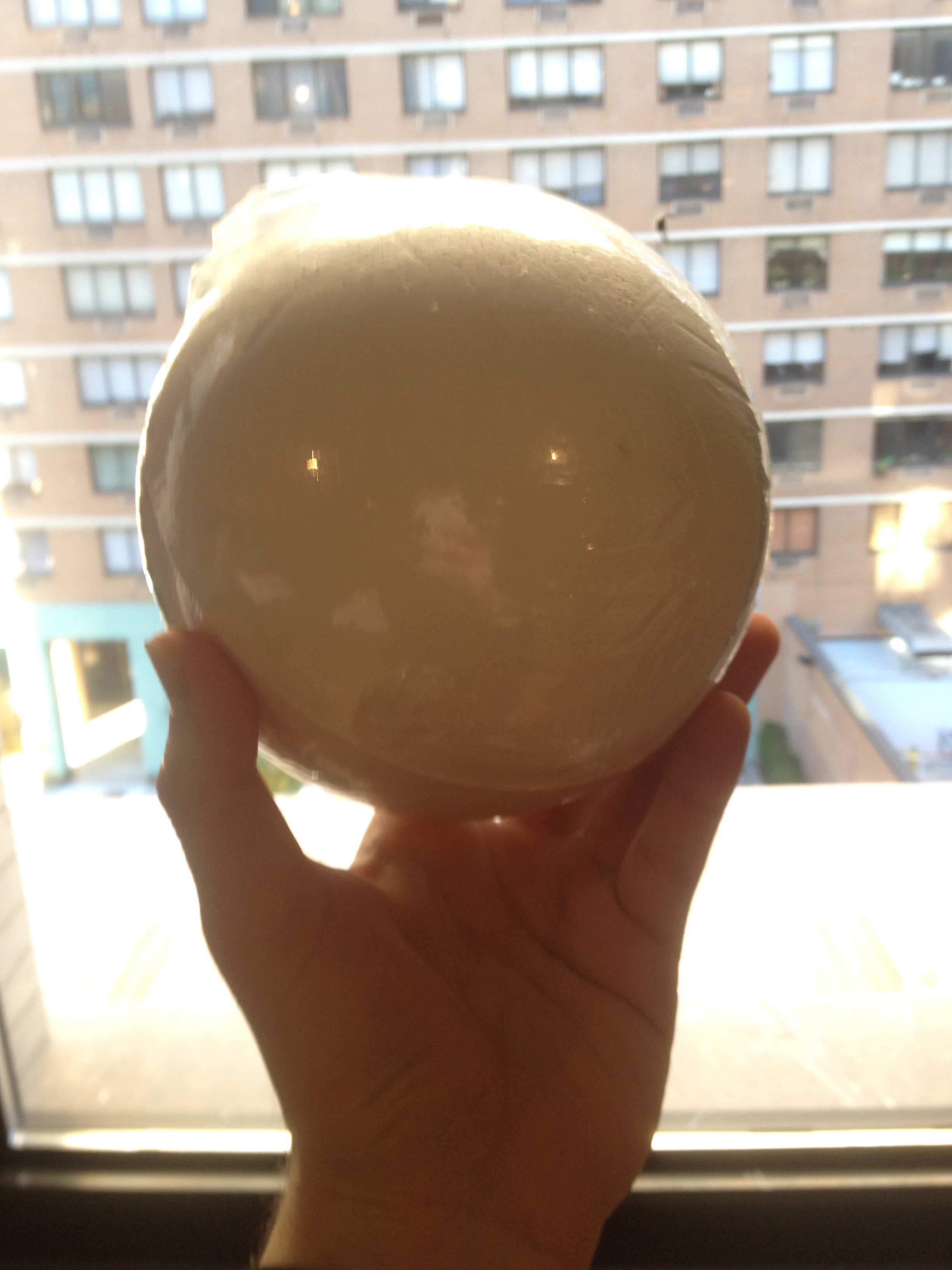
10/16/15
With some cutting and hollowing out, this foam sphere will act as the container for the accelerometer assembly.
10/16/15
Now I have the 3D P5 earth rotating with input from the accelerometer. Got a 9V battery to run the arduino independently of the laptop.
Now the only thing missing is a solid bluetooth connection. My bluetooth module connects with my laptop intermittently but no data comes in from the accelerometer to the computer once I disconnect the USB. I’ll have to get some help to troubleshoot it.
10/15/15
Got the 3D P5 earth rotation to work with dual potentiometers! One controls the X rotation and the other controls the Y rotation.
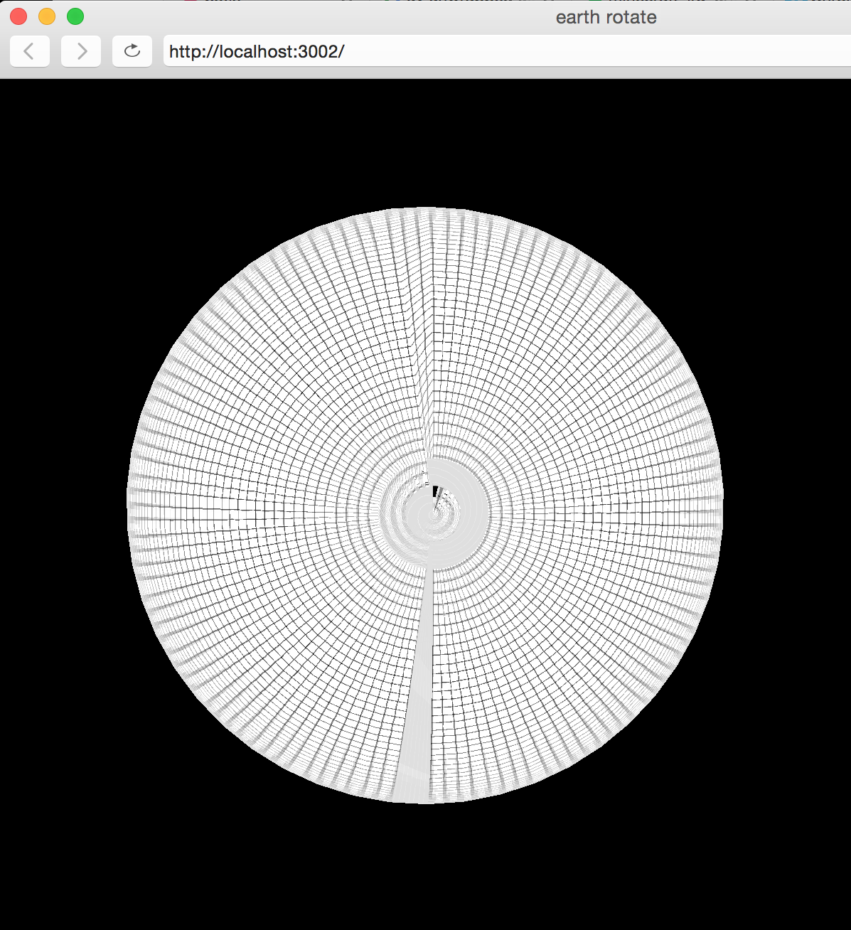
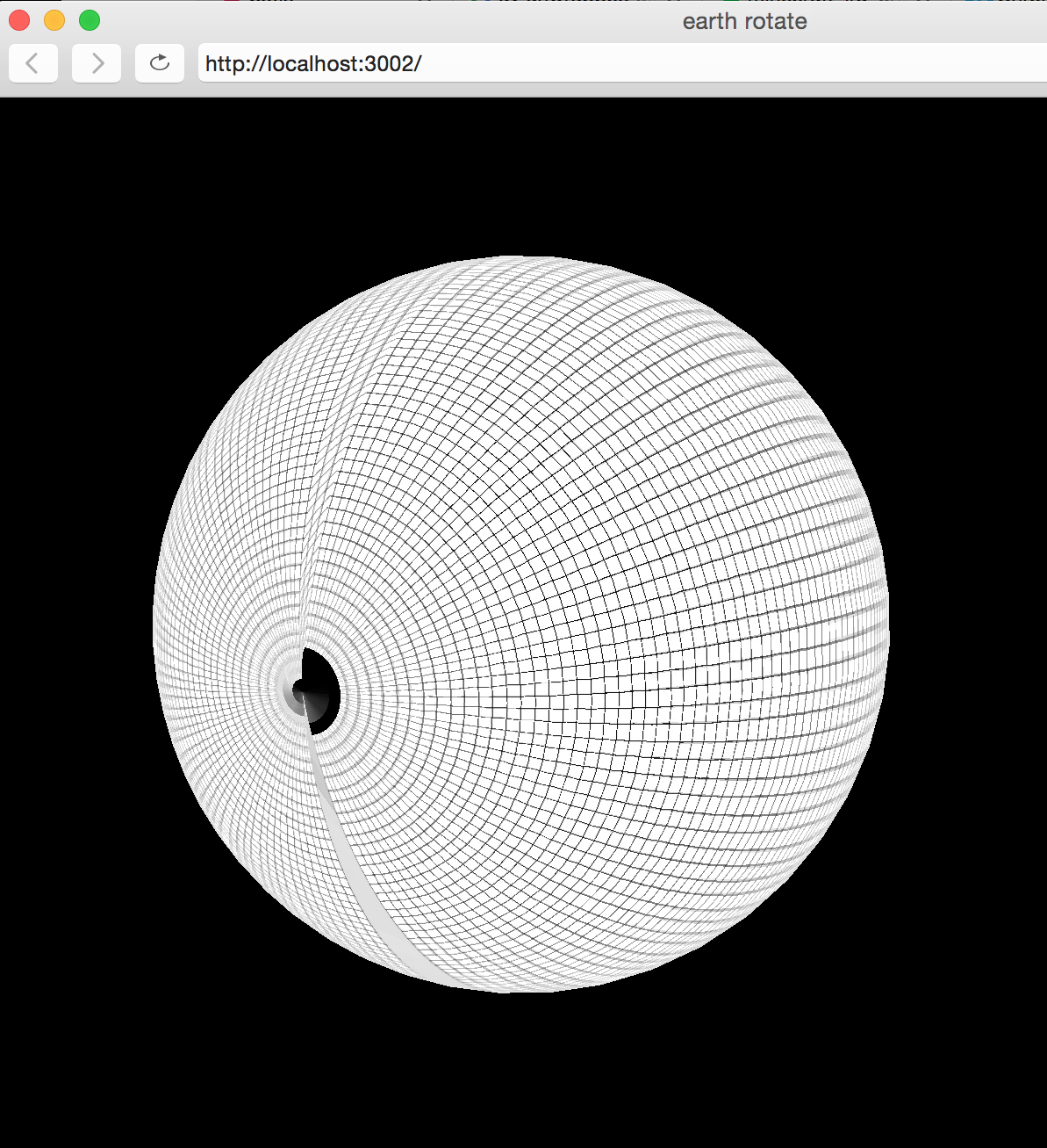
10/13/15
It took a while to get everything working again with my newest project. So many steps! This 3D object is texture mapped with an image of the earth. In the process I discovered that the normal mapping on the webgl sphere primitive is way off. I submitted a note to the p5 github page. As you can see from the grid mapped sphere there is tearing at the seam and other UV nasties.
Here is the a screenshot of the globe working with the potentiometer. I would like to figure out how to use more than one pot for additional interactivity.
10/7/15
“Get the small computer to talk to the big computer and vice versa”
This week we are delving more into the communication between P5 and the arduino board. Once the setup code is entered and communication is happening you can see the potential for digital and analog sensor use. Calibration becomes important. Also, some sensors are naturally more or less responsive than others. Thermistors are slow compared to photosensors for example. Need to come up with a good idea for the midterm project. By the way, this joystick is very neato. Steampunk innards that run four potentiometers.
10/6/15
I volunteered at this years Maker Faire at the Hall of Science in Queens. While I was there I got a chance to see the interactive installation called “Connected Worlds”.
Overall I think it is a very successful piece. Especially popular with children; it managed to hold their attention for a fairly long time. This animated, interactive projection installation sprawls across several walls of one of the larger spaces in the Hall of Science. With the correct gesture you can plant a seed, divert a river, help an animal, etc. Very diverse range of interaction events, all of which have some holistic effect on the entirety of the virtual ecosystem. Most simple gestures initiate an animated interaction, which prompts immediate engagement. The connectedness aspect might not be obvious to the user right away but the use of play is a great way to create an inception of the idea.
10/5/15
Got some practice time in on the laser cutter (for later projects).
10/2/15
During Synthesis Nikita and I were able to get a potentiometer to control the angle settings for this recursive code that draws an organic, curly tree shape. Lots of noise in the signal but I think we can smooth it out later.
9/30/15
Getting sensors to work with arduino code. Using adjustments in code to smooth out the function of a force resistor sensor. Use of the float function. Averaging values.
9/29/15
Playing around with a three axis accelerometer. The constant 10-9 read is gravity right?
Some experiments with potentiometer and piezo buzzer.
Potentiometer and speaker, took a while to get the arduino code to work right.
Finally got the dot matrix display to work for the most part.
9/25/15
Attended the NYC Media Lab conference. Lots of food for thought.
Especially enjoyed the presentation made by Conor Russomanno of OpenBCI, an open source, open hardware brain to computer interface startup.
http://openbci.com/
9/23/15
Servos are magical. Potentiometer to servo is a fun experiment.
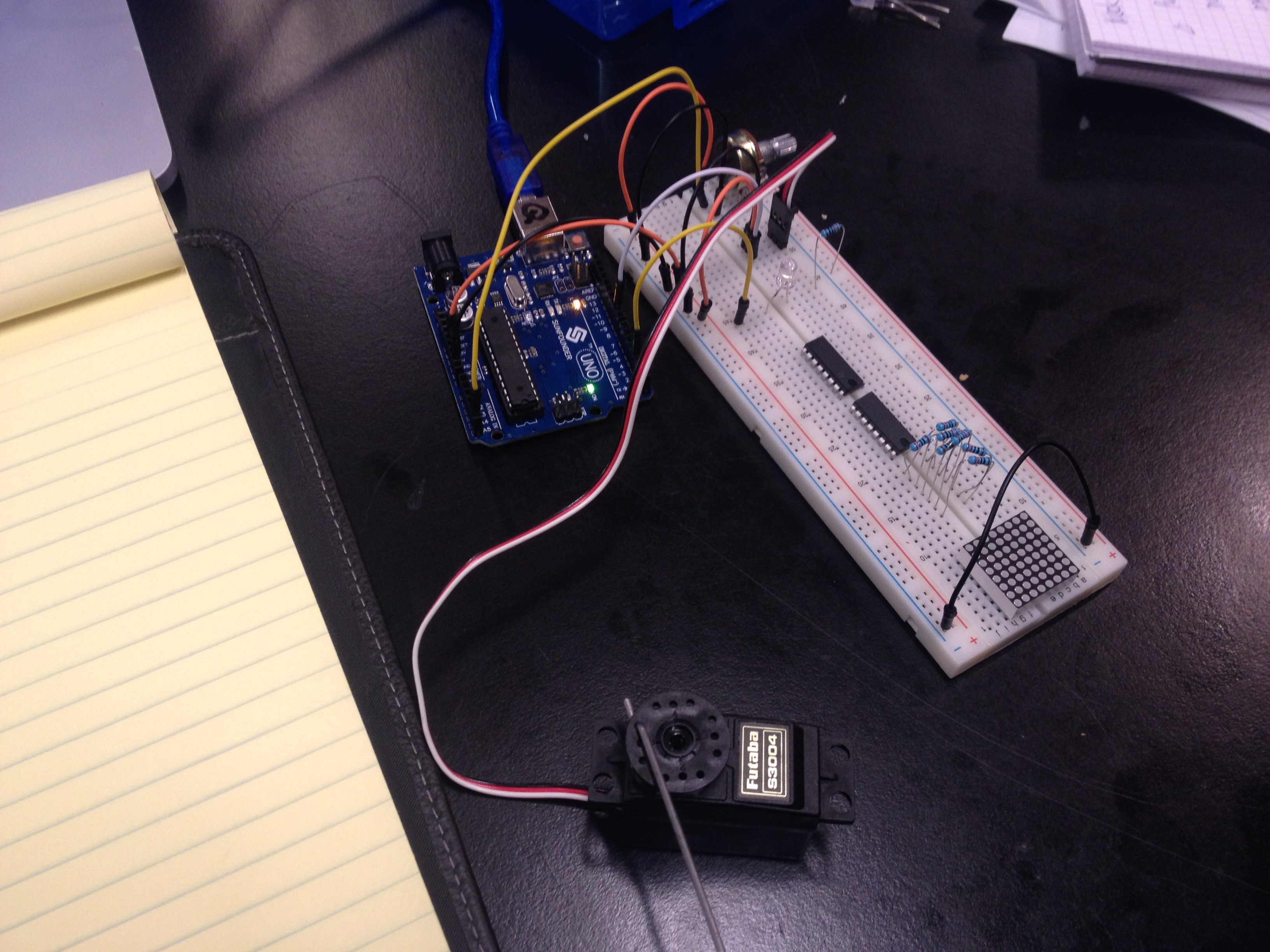
And who doesn’t love making noise?
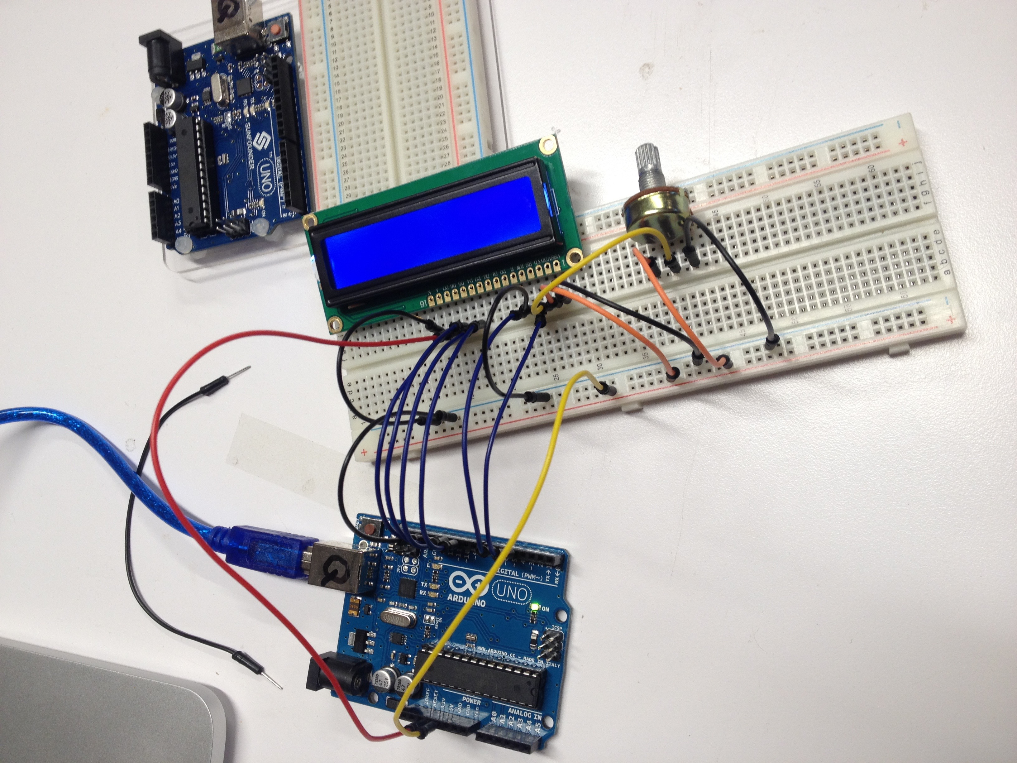
My project for arduino this week uses an LCD display and a button to create a primitive game. The user is sent messages of increasing urgency to stop pushing the button. How dire must the message be to stop the user from continuing to press the button? It took me quite a while to get the code to work properly. I had to learn how to “debounce” the button and time out the messages so that the button would continue to display a new message.
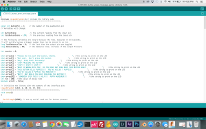
Project:
Code:
9/16/15
When writing code for Arduino or writing code in general it is best practice to use variables instead of “hard numbers” so that the code can easily be changed in the future and remains flexible. To save battery the sleep command may be used. A double == asks: “Is it equal?” Look into “pulling up” versus “pulling down” and how it relates to the position of resistors. The speed of communication with the Arduino should be set at 9600. Analog inputs do not require setup like digital ones. Analog gives a much larger range of input. A demonstration with a potentiometer and the readout screen shows variation from 0-1023 which is much more information than binary on and off.
Use digital input and output to create something and take the quiz on the class website…
9/15/15
Limited success with the LCD display, I’ll need to solder the pins to make it work properly.
Testing out a 3.3 Volt 3 watt higher power LED for another project. Bought from Tinkersphere.
Light switch with text input for LED action.
Fun with a digital 7 segment display, figured out how to get the entire countdown from 0-9 working in code. Video coming soon…
Still working on this one, dot matrix display, very complicated wiring diagram, need more color variety in my wires.
9/9/15
Basics of electronics. AC versus DC. Demonstrations of voltage, amperage and resistance. Using a multimeter. Opening and closing a circuit.
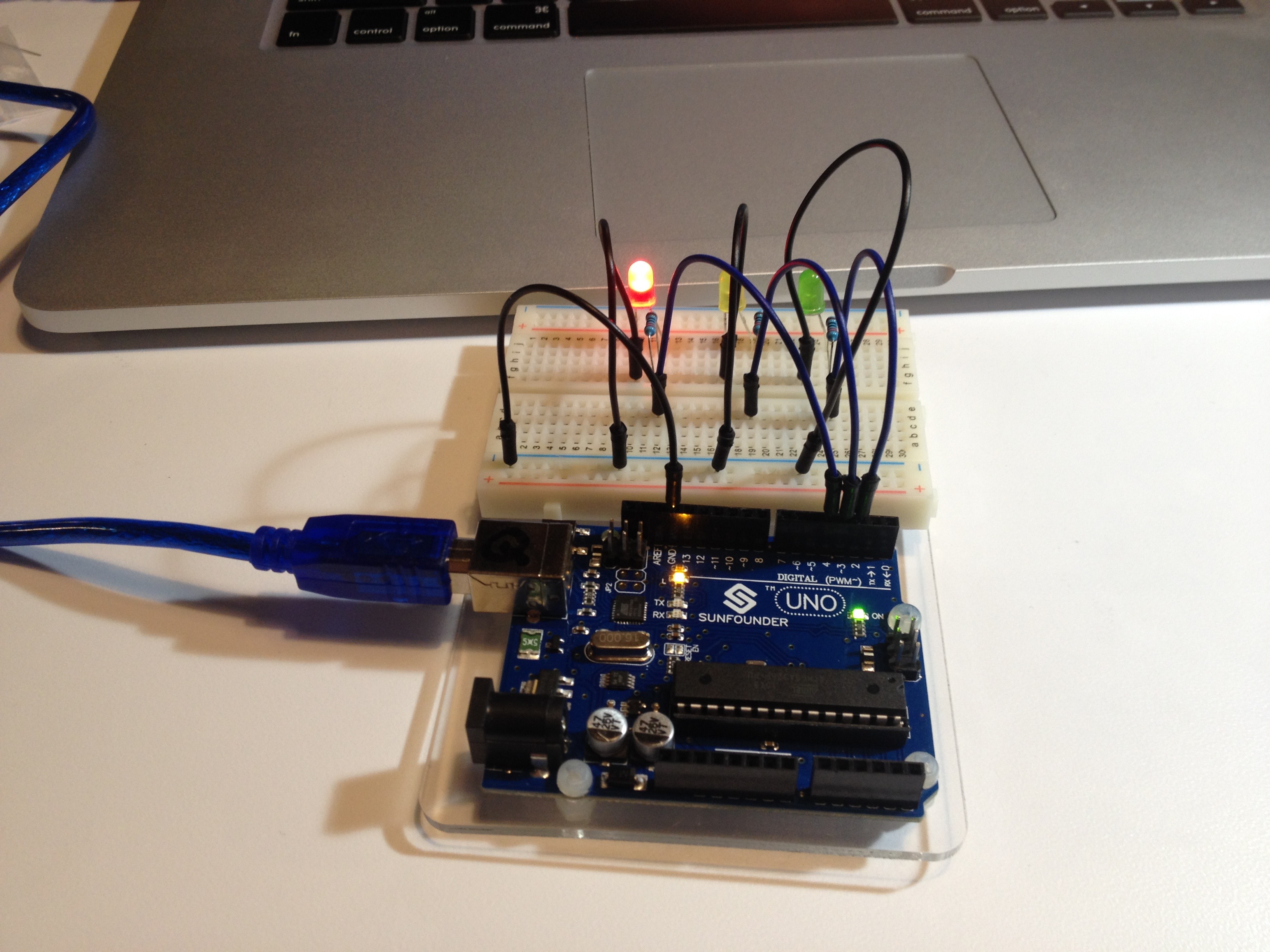
Outside of class I decided to run through the experiments in my “Sunfounder” Arduino kit. I really can’t resist playing with new tools. I ran through the following experiments after some initial frustration getting my computer to connect to the arduino board:
Blinking LED
Controlling an LED with a Button
Controlling LED by PWM
Controlling LED by Potentiometer
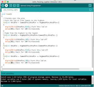
Flowing LED lights
I played around with the arduino code settings to make the flow faster, slower, reverse direction, etc.
RGB LED
Played around with the arduino code settings to get the LED to do specific colors.
DC Motor Control
9/5/15
Introductory blog post:
How would you define physical interaction? What makes for good physical interaction? Are there works from others that you would say are good examples of digital technology that are not interactive?
In terms of computing, I would define physical interaction as all forms of communication between the user and the computer that exists in the physical world. That would be the general sense of the term; expanding on that a bit; I think that physical interaction could be much more that it is. We do tend to click, scroll, swipe and wipe our way through mostly visual, and audio data as Bret Victor pointed out. Physical interaction could be much more holistic. It could be much more subtle. It could be much more tangible. Our devices could change shape, texture or weight. They could push back, shy away, shudder, shrink or grow. I think that what makes for good physical interaction is an efficient exchange of meaningful information in a way that captures the user’s attention. Novelty is valuable too. A good example of a non-interactive digital technology would be a piece of software that is hidden in a subfolder in a computer operating system and is never called upon to perform any function over the life of the computer.
9/2/15
“It’s all about us.”
Using technology to solve problems for people or groups of people.
Despite the widespread use of computers worldwide, most interaction with computers is limited to mouse movement and keyboard entry. What are some other modes of communication that humans use with each other that computers could potentially tap into? Verbal, non-verbal, gesture, touch, performance, etc.
P.S. Buy an Arduino Uno. Read: Crawford, The Art of Interactive Design, chapters 1 and 2 and Bret Victor, “A Brief Rant on the Future of Interaction Design”